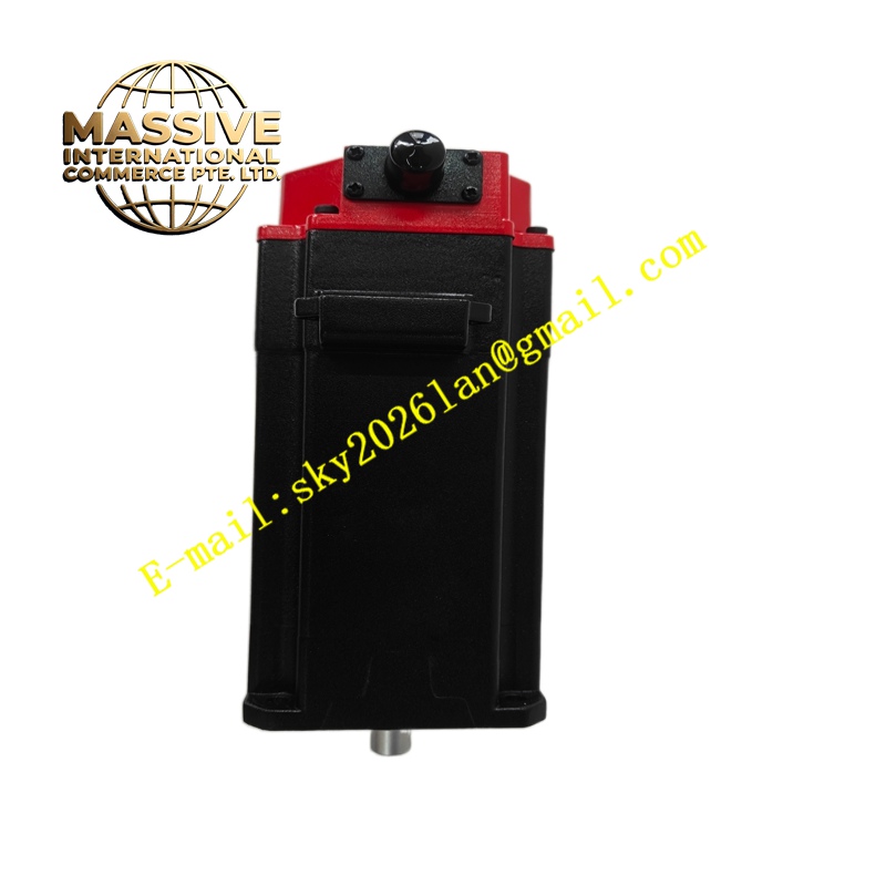
Description
GE A06B-1501-B105
Technical Specifications Wide constant power speed range; built-in spindle position sensor for orientation; three-phase AC input; liquid or air cooling optional structure; flange mounting; high dynamic rigidity; compatible with Fanuc spindle drive units.
Functional Features Provides high torque at low speed for heavy cutting and high rotational speed for high-speed finishing. Executes spindle orientation for tool change cycles. Supports rigid tapping synchronizing spindle rotation with Z-axis feed. Transmits spindle speed and position feedback signals to the spindle amplifier. Maintains stable rotation under varying cutting load.
Application Scenarios CNC milling machines, machining centers, heavy-duty lathes, high-speed engraving and cutting machine main spindle systems.
Performance Parameters Wide constant power zone; low rotational vibration at high speed; fast acceleration to target spindle speed; stable cutting performance under fluctuating chip load.
Material Composition Main housing uses cast aluminum alloy; stator is silicon steel laminated core with high-temperature magnet wire winding; rotor is forged alloy steel; front bearing set is high-precision angular contact bearing; position sensor housing is flame-retardant plastic.
Structural Characteristics Integrated spindle motor body; front bearing housing supporting tool shaft load; rear-mounted position detection sensor assembly; separate power connector and sensor signal connector; cooling channel embedded inside housing for thermal dissipation.
Working Principle The spindle amplifier outputs variable voltage and variable frequency three-phase power to the motor stator. The electromagnetic torque generated drives the rotor and tool spindle to rotate. The built-in position sensor captures rotor angular position for orientation and synchronous tapping. The drive adjusts output frequency and voltage continuously to maintain constant power within the designed speed band.
Installation Requirements Mount the motor on the machine spindle head with specified fasteners. Connect cooling piping if liquid cooling version is selected and verify flow rate. Separate power wiring from encoder signal wiring and use shielded cables. Configure spindle parameters including orientation angle and speed limit in the CNC system.
Precautions for Use Do not exceed the maximum continuous rotating speed specified in the rating plate. Monitor cooling temperature during heavy cutting cycles. Prevent cutting fluid and metal chips from entering the front bearing seal. Replace bearing sets according to the machine maintenance schedule.