Description
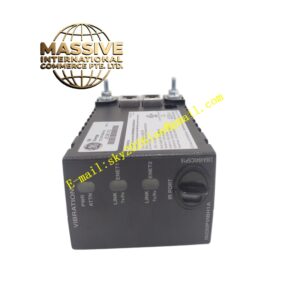
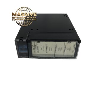
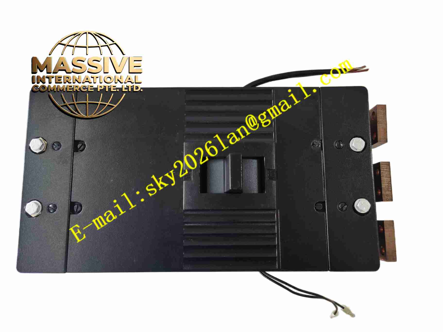
GE TKMA3Y1200
Technical Specifications Multiple relay output channels; Dry contact relay output; Rated contact load AC/DC; Backplane bus interface for GE control rack; Operating temperature -10°C to +60°C; LED per-channel status indicator; Isolation between control circuit and contact circuit; Rack plug-in design.
Functional Features Galvanic isolation between control logic side and field contact side; Individual LED shows relay actuation state; Relay contact dry contact output supports mixed AC and DC field circuits; Backplane communication exchanges command and diagnostic data with rack controller; Contact state diagnostic; Module fault signal upload to main controller; Supports hot swap in qualified rack configuration.
Application Scenarios Power plant DCS auxiliary control; Boiler valve interlock control; Substation auxiliary relay control; Chemical plant alarm and trip circuit; Water treatment plant actuator control; Cement plant process interlock system.
Performance Parameters Relay contact switching speed stable; Contact insulation withstand voltage high; Channel state diagnostic response rapid; Backplane communication latency constant; Contact mechanical service life meets industrial control requirement.
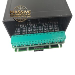
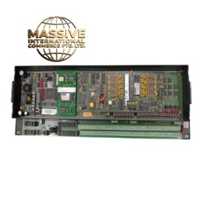
Material Composition Flame-retardant plastic module housing; Electromechanical signal relays; Glass fiber printed circuit board; Backplane bus transceiver chip; Screw terminal blocks for field contact wiring; LED status indicators; Gold-plated backplane connector.
Structural Features Plug-in module for GE standard control rack; Rear gold-plated connector connects rack backplane; Front panel terminal blocks and LED indicators; Locking latch to secure module in rack; Internal isolation barrier separates backplane logic circuit and relay contact circuits.
Working Principle Main controller sends digital output command over rack backplane bus to TKMA3Y1200 module. Onboard logic circuit receives command and energizes corresponding relay coil. Relay contact closes or opens to switch external field circuit. LED indicator lights up to show relay actuation state. The module monitors relay driving state continuously and uploads fault information to controller once abnormality is detected. Dry contacts provide fully isolated switching for field loads.
Installation Requirements Insert module into compatible GE rack slot and lock latch; Field contact wiring torque matches terminal specification; Separate field load wiring from low-voltage control wiring; Rack cabinet protective earth connection required; Use surge suppression components for inductive field loads.
Precautions for Use Do not exceed rated contact voltage and current; Cut off field load power before wiring maintenance; Verify hot swap permission before module replacement; Check relay contact condition after long-term operation; Avoid installation in high humidity and corrosive gas environment.