Description
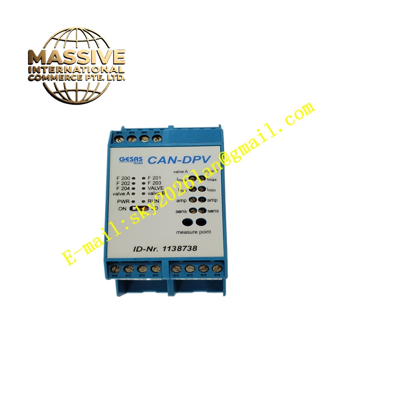
GESAS CAN-DPV
Technical Specifications CAN 2.0B communication protocol. Multi-channel analog voltage input. Input signal range 0-10V. 24V DC power supply. Galvanic isolation between field analog channels and internal bus circuit. High-resolution analog-to-digital conversion. Configurable sampling frequency. Operating temperature -20°C to +60°C. IP30 protection grade.
Functional Features Sample continuous analog voltage signals from pressure, temperature and displacement transmitters. Convert analog signals into digital measurement values through high-precision ADC chips. Transmit measurement data to master controllers or other CAN bus nodes cyclically. Receive configuration commands from the bus to adjust sampling frequency, signal range and filtering parameters. Diagnose channel over-range, open circuit and power supply abnormal conditions and send alarm messages. Support parameter saving after power failure.
Application Scenarios Mobile hydraulic equipment pressure monitoring, industrial temperature transmitter signal collection, material thickness detection, distributed test system analog signal acquisition, off-highway machinery parameter monitoring.
Performance Parameters High analog conversion precision. Low temperature drift of sampling channels. Digital filtering function suppresses high-frequency noise. Stable data transmission on CAN bus. Over-range alarm response without delay.
Material Composition PCB substrate is FR-4 flame-retardant multilayer board. Analog front end uses precision operational amplifiers and ADC chips. CAN transceiver has surge protection components. Signal isolation adopts optocoupler and isolation power supply. Enclosure is flame-retardant engineering plastic. Terminal contact materials are nickel-plated copper alloy.
Structural Characteristics DIN rail compact plastic housing. Front panel is equipped with power LED, bus communication LED and channel status indicators. Upper and lower screw terminals are used for 24V power, CAN bus wiring and analog sensor signal wiring. Internal layout separates analog weak signal area and digital bus circuit to reduce crosstalk.
Working Principle Analog voltage signals from field sensors enter the signal conditioning circuit for impedance matching and noise filtering. The conditioned signals are sent to the analog-to-digital converter to generate digital measurement values. The microcontroller packs measurement data into CAN protocol frames and sends them to the bus. The module receives remote configuration instructions and adjusts sampling and filtering parameters in real time, and reports channel faults when signals exceed the set range.
Installation Requirements Fix the module on standard DIN rail in the control cabinet. Connect shielded twisted-pair wires for analog sensors and CAN bus. Complete bus baud rate, node address and channel range configuration through supporting software. Perform signal calibration for each analog channel. Check data upload stability on the CAN network after commissioning.
Precautions for Use Use shielded cables for analog signal wiring and implement single-point grounding of shielding layer. Keep analog signal cables away from motor power cables and frequency converter output lines. Do not input voltage beyond the 0-10V rated range. Add surge protection devices for field sensors installed in exposed environments. Power off the module before changing wiring.