Description
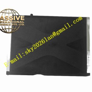
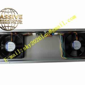
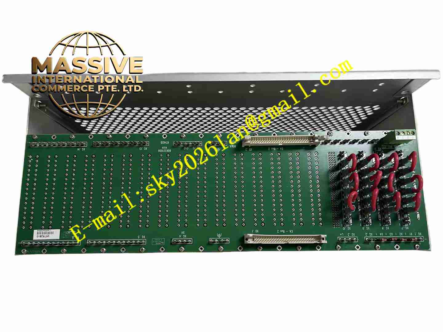
HIMA EABT3 B9302 997009302
Technical Specifications
- Product Type: Safety-related digital output module
- Number of Channels: 8 independent digital output channels
- Output Voltage: 24 VDC high-side switching
- Continuous Current Rating: Channels 1,2,3,5,6,7: 0.5 A; Channels 4,8: 1 A continuous, peak up to 2 A
- Safety Certification: SIL3, TÜV certified
- Protection Rating: IP20
- Operating Temperature Range: -10 °C to +60 °C
- Storage Temperature Range: -20 °C to +75 °C
- Communication: Internal HIMA safety bus backplane communication
- Fault Detection: Short-circuit detection, overload detection, channel diagnostic monitoring
- Indicator: Individual LED status indicator for each channel
- Mounting: DIN rail rack mounting inside control cabinet
Functional Features
- 8 galvanically separated safety output channels for driving solenoid valves, relays and safety actuators.
- Built-in continuous self-diagnosis on every channel during operation.
- Automatic channel shutdown upon overload or short-circuit occurrence, with fault signal transmission to safety CPU.
- Independent LED indicators display power status, run state and channel fault information.
- Safe de-energization logic to trigger emergency shutdown when safety trip condition activates.
- Backplane safety bus provides secure, error-checked data communication with the HIMA safety controller.
- Hot-swap compatible within approved system configuration without full system shutdown.
- Hardware fault voting mechanism to prevent unsafe output state caused by single component failure.
- Over-temperature protection cuts off channel output when internal temperature exceeds threshold.
- Supports safety system partial stroke test for final control elements.
Application Scenarios
- Emergency shutdown system in petrochemical and refinery plants
- Boiler and furnace burner management safety control
- Oil & gas offshore platform safety interlock systems
- Chemical reactor safety protection
- Power plant boiler safety trip systems
Material Composition
- Module housing: Flame-retardant polycarbonate plastic
- Main circuit board: FR4 high-temperature PCB with conformal coating
- Power switching components: Industrial grade MOSFET and safety relays
- Terminal block: Copper alloy spring cage wiring terminals
- Backplane connector: Gold-plated copper contact pins
- Internal encapsulation: High-stability insulating compound for critical circuits
Structural Characteristics
- Standard modular vertical rack structure matching HIMA F35 rack system.
- Front panel fitted with channel LED indicators and module status LEDs.
- Lower section contains field wiring terminals for 24VDC output wiring.
- Rear edge gold-plated connector inserts into safety backplane bus.
- Internal circuit layout separates safety logic circuit and power output circuit.
- Metal shielding layer reduces electromagnetic interference impact.
Working Principle The safety CPU sends validated safety commands through the backplane bus to the module. The internal safety logic circuit verifies command integrity twice before activating output switches. The MOSFET power switches control 24VDC power supply to field actuators. Every channel continuously monitors output current and voltage. When short-circuit, overload or internal circuit failure is detected, the module immediately de-energizes the corresponding channel and reports fault code to the safety controller. The dual diagnostic path prevents false safe or unsafe outputs under single failure condition.
Installation Requirements
- Install on standard DIN rail inside dust-free industrial control cabinet.
- Insert module securely into HIMA F35 series safety backplane rack.
- Use shielded twisted pair cables for field actuator wiring.
- Separate safety output cables from high-power motor cables.
- Complete protective earth connection for the rack and cabinet.
- Keep clearance between adjacent modules for air circulation.
- Verify backplane bus connection and terminal wiring before power on.
- Perform full module diagnostic test after installation.
Usage Notes
- Do not plug or unplug the module when system power remains active.
- Do not exceed rated channel current for each output channel.
- Keep cabinet free of corrosive gas, oil mist and conductive dust.
- Conduct periodic full system proof test as required by SIL safety procedures.
- Disconnect field wiring before insulation resistance test.
- Store spare modules in anti-static packaging and dry warehouse.
- Replace module immediately when persistent internal hardware fault occurs.