



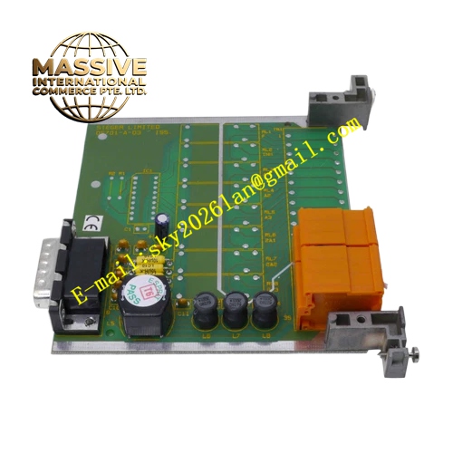
Description
Honeywell 05701-A-0326
Technical Specifications
- Channel Configuration: Dual SPCO relay contact groups
- Relay Contact Rating: 2 A @ 250 VAC resistive load
- Backplane Interface: System 57 rack proprietary parallel bus
- Logic Supply: 24 VDC from rack backplane
- Operating Temperature: -10 °C to +55 °C
- Humidity: 10 % to 90 % non-condensing
- Isolation: Reinforced isolation between backplane logic circuit and relay field contacts
- Form Factor: Standard 19 inch rack plug-in eurocard
Functional Features Each relay channel provides normally open and normally closed dry contact terminals for flexible alarm wiring configuration. Contact feedback circuit reads actual relay armature state and compares against commanded state to detect relay sticking failure. Front panel LED shows power status, relay energized state and internal fault flag. Backplane communication frames include checksum validation to reject corrupted commands. Output contact suppression network absorbs inductive kickback voltage from external alarm loads. Card fault signal is transmitted to main system controller and recorded in event log with timestamp.
Application Scenarios Fixed gas detection panel alarm horn and strobe light control Flammable gas emergency shutdown valve interlock relay drive Toxic gas monitoring system alarm escalation logic output Oil and gas platform, chemical plant gas detection rack spare replacement
Performance Parameters
- Relay Operating Time: ≤15 ms
- Relay Release Time: ≤10 ms
- Contact Mechanical Life: 10,000,000 cycles minimum
- Contact Electrical Life: 200,000 cycles under full rated resistive load
- Diagnostic fault reporting latency: Less than 200 ms
- Isolation withstand voltage: 1500 VAC between logic and field terminals for 60 seconds
Material Composition PCB substrate: FR4 multilayer flame retardant board Relay devices: Hermetically sealed electromagnetic signal relays with silver alloy contacts Isolation components: Optocoupler isolation chips Suppression components: Metal oxide varistors and flyback diodes Terminal block: Screw type tin plated copper terminal strip Card housing: Black UL94 V0 plastic front panel assembly
Structural Features Eurocard size PCB compatible with System 57 8-slot or 16-slot rack chassis. Front panel equipped with transparent window for LED observation and card extraction handle. Rear gold plated edge connector mates with rack backplane bus pins. Screw terminal block mounts at front lower section for field wiring access. Internal isolation barrier separates low voltage logic zone and high voltage relay contact zone. Keying notch prevents insertion into incompatible card slots.
Working Principle System 57 main controller sends relay set or reset command through rack backplane bus. Onboard logic IC validates frame integrity and triggers corresponding relay driver circuit. Relay coil energizes and moves contact armature to switch field circuit path. Feedback sampling circuit detects contact terminal potential and sends real contact status back to controller. If commanded state differs from feedback state, fault flag is asserted and alarm message appears on system display.
Installation Requirements Insert card only when rack main power supply is de-energized. Field wiring to relay terminals must use separate cable duct away from gas sensor signal cables. Set external surge suppression for long cable runs connected to inductive alarm devices. Tighten terminal screws to specified torque value to avoid high resistance contact. Confirm rack firmware version compatibility before commissioning.
Usage Notes Do not exceed 2 A contact rating on each relay channel. Do not connect live high voltage wiring while card remains plugged into powered rack. Contact arcing will degrade contact life under inductive load, external snubber circuit is mandatory. Card must stay inside listed System 57 rack enclosure to maintain certification compliance.







