



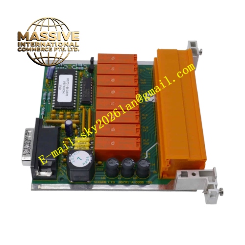
Description
Honeywell 05701-A-0330
Technical Specifications Nominal supply 24VDC DC power Operating consumption 100mA Compatible with Honeywell 05704 series UV flame sensors Fixed flame failure response delay of 1 second Relay output contact rated 5A 240VAC Operating temperature range -20℃ to 70℃ Storage temperature -40℃ to 85℃ Humidity 5% to 95% non-condensing Diagnostic coverage for open and short sensor circuits
Functional Features It converts weak UV sensor pulses into stable flame status relay output. It suppresses noise pulses from ignition sparks and electric arcs. It implements fixed flame loss timer to avoid nuisance tripping from momentary flame flicker. It energizes the flame relay when continuous valid flame signal is received. It de-energizes relay and triggers safety shutdown when flame signal disappears beyond set delay. It lights fault indicator upon sensor wiring failure.
Application Scenarios Burner flame supervision for small industrial hot water boilers Flame detection control for packaged gas burners Heating furnace flame safeguard in rubber and plastic factories Thermal oil heater flame monitoring Auxiliary burner interlock protection for drying systems
Performance Parameters Signal noise rejection capability exceeds 35dB Relay switching time is less than 20ms Diagnostic circuit identifies probe short or open circuit within 300ms Relay contact life exceeds 8 million switching cycles
Material Composition PCB substrate is FR4 flame retardant material with protective coating Core signal processing devices are industrial operational amplifiers Output relay adopts silver alloy contacts Module housing is flame retardant black ABS plastic Terminal blocks use heat-resistant nylon insulation
Structural Characteristics Standard DIN rail mount plastic enclosure Front panel has LED indicators for power, flame present and fault status Screw terminals are arranged along the bottom edge for power input, sensor connection and relay output Internal circuit boards are fixed with anti-vibration supports Enclosure protection grade reaches IP20
Working Principle Pulse signals from UV flame detector enter the amplifier input terminals. The internal filter network removes high-frequency interference pulses. The comparator circuit checks if pulse frequency and amplitude meet flame criteria. When valid flame pulses persist for the required time, the flame relay energizes. When pulses stop for longer than fixed delay, the relay drops out and sends flame trip signal to burner controller. The diagnostic circuit monitors probe loop resistance continuously.
Installation Requirements Clip the module onto standard 35mm DIN rail inside control cabinet Run shielded cable between amplifier and UV probe Separate signal wiring from ignition high voltage wiring Tighten terminal screws to specified torque Confirm correct polarity of 24VDC supply before powering up
Usage Notes This model uses fixed flame failure delay without adjustable timer Do not use for large boiler critical burners requiring custom flame response timing Perform flame simulation test after wiring and power on Keep cabinet internal temperature within rated operating range







