



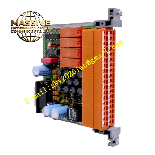
Description
Honeywell 05704-A-0121
Technical Specifications Monitor multiple DC power rails of System 57 rack; voltage and current sampling circuit; built-in temperature sensing element; backplane communication with rack controller; operating temperature 0℃ to 55℃; storage temperature -40℃ to 85℃; humidity 5% to 95% non-condensing; fault threshold configurable through rack software.
Functional Features It samples real-time voltage and current values of each power rail inside the gas rack. It detects power module over-temperature state via on-board temperature sensor. It compares sampled parameters with preset fault thresholds. It uploads power abnormal alarm and power health data to the System 57 rack controller. It provides power status indication on the front panel LEDs.
Application Scenarios Power health monitoring for refinery System 57 gas detection racks; power fault diagnosis for chemical plant gas safety cabinets; spare monitoring card replacement for System 57 rack maintenance projects; power supervision for offshore platform gas monitoring systems.
Performance Parameters Voltage sampling accuracy meets rack power diagnosis requirement; temperature sensor response is continuous; fault judgment logic will not generate false alarm under normal power fluctuation; parameter update cycle matches rack diagnostic scan rate.
Material Composition Circuit board is FR4 flame retardant PCB with conformal coating; precision sampling resistors and voltage reference chips; on-board NTC temperature sensor; gold-plated backplane edge connector; front panel cold rolled steel with corrosion resistant coating.
Structural Characteristics Vertical plug-in card for System 57 rack; front panel equipped with power normal and power fault LED indicators; elastic locking latches on both sides; passive convection cooling; keyed edge connector for preventing misinstallation.
Working Principle The module obtains sampling signals from rack power rails through backplane traces. The sampling circuit converts voltage, current and temperature into digital values. The on-board logic compares measured values with alarm thresholds. When parameters exceed normal range, the module sends fault alarm message to the rack controller through backplane communication bus.
Installation Requirements Install the card in the dedicated supervision slot of System 57 gas rack. Confirm backplane contact pins are fully seated. Configure power alarm thresholds through System 57 rack configuration software. Keep cabinet ventilation to avoid local overheating. Cabinet grounding resistance ≤4Ω.
Usage Notes Do not modify sampling circuit components on site. Verify power alarm function by simulating fault condition after replacement. Wear anti-static wrist strap when handling the card. Keep the card surface free of dust accumulation.







