



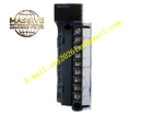
Description
Honeywell 2MLF-AD8A-CC
Technical Specifications
- Channel count: 8 analog input channels
- Signal types: 4–20 mA, 0–10 V DC
- Resolution: 12-bit ADC
- Channel isolation: 500 VAC per channel
- Backplane interface: MasterLogic 200 expansion bus
- Supply power: 5 V DC from backplane, 24 V DC field power
- Operating temperature: 0 °C to +55 °C
Functional Features Software-configurable per-channel input type, no hardware jumpers required. Per-channel overvoltage protection, clamps transient voltage spikes. Digital filter smooths sampled values, suppresses field signal noise. Module status LED indicates power, normal operation and fault. Hot swap support, module replacement without full system shutdown. Input range scaling configured via PLC programming software.
Application Scenarios MasterLogic 200 PLC temperature and pressure signal acquisition Industrial process analog sensor integration Expansion for PLC systems requiring additional analog points Spare part replacement for failed analog input modules
Performance Parameters
- Conversion accuracy: ±0.1% full scale
- Update rate: 10 ms per channel
- Common mode rejection ratio: ≥80 dB
- Input impedance: 100 kΩ for voltage, 250 Ω for current
- Mean time between failures: 500,000 hours
Material Composition ABS flame retardant housing 12-bit ADC chip TVS surge protection diodes Removable screw terminal block Gold-plated backplane connector Epoxy PCB
Structural Features Narrow rectangular DIN-rail mount housing. Front removable terminal block for field wiring. Side expansion bus connector mates to adjacent PLC modules. Front status LEDs for power and fault. DIN rail mounting clip.
Working Principle Field sensor signals connect to the input terminals. Each channel routes to the 12-bit ADC, converting analog voltage or current values to digital counts. The module logic packages channel data into expansion bus frames, transmitting to the PLC CPU. Digital filter averages consecutive samples to reduce noise. Per-channel configuration registers store input range settings, scaling raw counts to engineering units. Surge protection diodes clamp transient voltage before it reaches the ADC input.
Installation Requirements Clip the module to the DIN rail adjacent to the CPU. Connect the expansion bus connector between modules. Wire field sensors to labeled channel terminals. Configure input type and scaling in the PLC programming software. Verify channel values read correctly after power-up.
Usage Notes Never apply 24 V DC to 0–10 V input channels, this damages the ADC. Shielded cable for current loop sensors reduces EMI interference. Removable terminal blocks must be fully seated; loose connections cause channel dropout. Route analog wiring separately from high-voltage power cables.







