



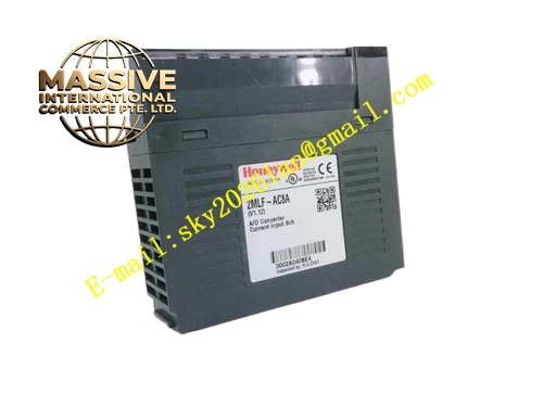
Description
Honeywell 2MLF-DC8A-CC
Technical Specifications
- Channel count: 8 analog output channels
- Signal types: 4–20 mA, 0–10 V DC
- Resolution: 12-bit DAC
- Channel isolation: 500 VAC per channel
- Backplane interface: MasterLogic 200 expansion bus
- Supply power: 5 V DC from backplane, 24 V DC field power
- Operating temperature: 0 °C to +55 °C
Functional Features Software-configurable per-channel output type. Per-channel short-circuit protection, limits output current on field wiring faults. Output readback sampling, compares actual output to commanded value. Module fault LED indicates short circuit or over-temperature. Hot swap support, module replacement without system shutdown. Configurable fail-safe output value on CPU stop.
Application Scenarios MasterLogic 200 process control loop analog output Proportional control valve and actuator drive VFD speed reference signal output Spare part replacement for failed analog output modules
Performance Parameters
- Output accuracy: ±0.2% full scale
- Update rate: 10 ms per channel
- Maximum load: 500 Ω for current output, 2 kΩ minimum for voltage output
- Short circuit protection: 25 mA current limit
- Mean time between failures: 400,000 hours
Material Composition ABS flame retardant housing 12-bit DAC chip Output operational amplifier array TVS protection diodes Removable screw terminal block Gold-plated backplane connector
Structural Features Narrow rectangular DIN-rail mount housing. Front removable terminal block. Side expansion bus connector. Front power and fault status LEDs. DIN rail mounting clip.
Working Principle The PLC CPU sends setpoint values over the expansion bus to the module. Each channel routes values to the 12-bit DAC, converting digital commands to analog voltage or current signals. Operational amplifiers drive the field load at the configured output level. Readback circuit samples actual output voltage or current; deviation between command and measured value triggers a channel fault alarm. On CPU stop, outputs default to the pre-configured fail-safe value. Short-circuit protection limits output current to 25 mA on field wiring faults.
Installation Requirements Clip the module to the DIN rail next to the CPU. Connect expansion bus cables between modules. Wire field actuators to output terminals. Configure output type and fail-safe value in PLC software. Verify output values scale correctly after power-up.
Usage Notes Current output loop load must not exceed 500 Ω, higher impedance causes voltage droop. Never short-circuit output terminals repeatedly; repeated short circuits damage the output driver. Shielded cable for analog output reduces noise on control signals. Never apply external voltage to output terminals, reverse voltage destroys the DAC.







