



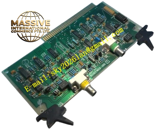
Description
Honeywell 51107403-100
Technical Specifications
- Communication Standard: Honeywell proprietary LCN bus
- Media Interface: Coaxial cable BNC connector
- Bus Data Rate: Fixed LCN network baud rate
- Impedance Matching: 75 Ω precision termination network
- Operating Temperature: 0 °C to +60 °C
- Isolation: Transformer isolation between node logic circuit and coaxial cable side
- Board Form: Small daughter card plugging into LCN node motherboard
Functional Features Precision resistor termination network matches 75 ohm coaxial cable characteristic impedance to eliminate signal reflection. Transformer galvanic isolation blocks common mode noise and ground loop current between node chassis and cable shield. Signal buffer amplifier reshapes distorted LCN waveform for long cable transmission. Line fault detection monitors carrier presence and reports cable loss to node diagnostic register. Surge protection circuit absorbs electrostatic discharge and transient surge from field coaxial cable.
Application Scenarios TPS LCN node communication failure replacement LCN network intermittent communication fault maintenance Control room LCN backbone network signal integrity improvement Legacy DCS system annual overhaul spare part
Performance Parameters
- Return loss at LCN working frequency: >20 dB
- Isolation withstand voltage: 1000 VAC between logic side and cable side
- Surge withstand capacity: 2 kV ESD contact discharge
- Fault reporting latency: Less than one LCN communication cycle
Material Composition High TG FR4 PCB, wideband pulse transformer, precision 75 Ω metal film resistors, ferrite noise suppression beads, TVS surge diodes, BNC coaxial connector, gold plated board-to-board socket connector.
Structural Features Compact rectangular daughter board with single edge gold connector for mating with node motherboard socket. One BNC coaxial connector mounted on board edge for LCN trunk cable connection. No front panel, fully installed inside LCN node chassis. Component layout minimizes trace length for high frequency signal path. Silk screen orientation marking prevents reverse plugging.
Working Principle Digital LCN communication signal from node motherboard passes through buffer circuit and isolation transformer, then drives 75 ohm coaxial cable. Incoming signal from LCN cable flows through termination network and isolation transformer before reshaping and sending to node communication logic. Loss of carrier signal or severe waveform distortion triggers cable fault alarm to controller diagnostic log.
Installation Requirements Power down LCN node chassis completely before board replacement. Align orientation mark and insert daughter board fully into motherboard socket. Connect LCN coaxial trunk cable to BNC connector and hand-tighten lock nut. Verify LCN node online status and network communication after power restoration.
Usage Notes Improper termination causes LCN network packet loss and intermittent node dropout. Do not bend coaxial cable sharply near BNC connector. Anti-static wristband must be worn during handling to protect high speed components. Do not modify onboard termination resistor value.







