



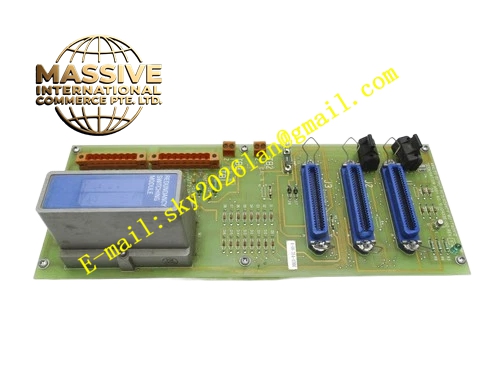
Description
Honeywell 51108306-200
Technical Specifications
- Communication Bus: TDC3000 LCN bus, 5Mbps transmission rate
- Signal Medium: 75Ω coaxial cable
- Power Supply: 5VDC and 12VDC supplied from rack backplane
- Operating Ambient Temperature: 0°C to +60°C
- Storage Temperature: -40°C to +85°C
- Relative Humidity: 5% to 90% RH non-condensing
- Mounting Type: Plug-in slot installation on TDC3000 main control rack
- Certification: UL, CE, RoHS
- Impedance Matching: 75Ω nominal impedance
- Channel Quantity: Dual LCN channel support
Functional Features It receives analog LCN carrier signal from coaxial cable and converts weak high-frequency signal into digital logic level. It reshapes distorted communication frames and eliminates signal attenuation caused by long cable transmission. It monitors signal amplitude and carrier presence status of LCN A and LCN B channels independently. It triggers automatic channel switchover when active LCN link loses carrier signal. It verifies frame checksum and filters noise-induced invalid packets. It uploads link status, frame error count and disconnection fault log to TDC3000 operator station. It carries front panel LED indicators for power, LCN A active, LCN B active and communication fault. It supports hot swap replacement under redundant node configuration. It stores network diagnostic history in on-board non-volatile memory.
Application Scenarios Petrochemical plant TDC3000 control node LCN network access cabinet Refinery furnace control rack LCN coaxial interface module Power plant boiler interlock control node LCN communication interface Chemical plant batch control system redundant LCN link rack Natural gas pipeline station TDC3000 remote node network interface
Performance Parameters
- Redundant Channel Switchover Time: Less than 60ms
- Mean Time Between Failures: 860000 hours
- ESD Immunity: 8kV contact discharge
- Maximum Supported LCN Cable Length: 2000 meters
- Signal Amplitude Recovery Accuracy: ±5%
Material Composition FR4 flame retardant conformal coated multilayer PCB High-speed differential signal amplifier array LCN PHY transceiver chip Impedance matching precision resistor network Isolation transformer and TVS surge suppression components Gold plated edge connector for TDC3000 backplane Metal front panel with extraction handle, coaxial signal ports and LED indicators Internal controlled impedance signal traces for high-speed LCN signal
Structural Features Standard paddle card form factor. Front panel integrates dual LCN coaxial BNC ports, grouped LED indicators and extraction handle. Rear gold plated edge connector mates with rack backplane power and logic bus. Independent shielding cavity separates LCN A and LCN B signal circuits to avoid cross-talk. Anti-key notch prevents reverse insertion into rack slot. Locking clip secures module firmly after installation. PCB traces adopt strict 75Ω controlled impedance design to guarantee signal integrity. Conformal coating fully covers PCB surface to resist dust, moisture and corrosive gas in industrial cabinet environment.
Working Principle After receiving 5VDC and 12VDC power supply from rack backplane, the module completes power-on self-test and impedance calibration. LCN carrier signal enters the amplifier circuit through BNC port. Amplifier circuit restores attenuated signal amplitude to the standard logic level. Transceiver chip demodulates carrier signal into digital communication frames. Logic chip verifies frame validity and forwards valid frames to the node main processor. If active channel carrier signal disappears continuously, the module switches all communication traffic to standby LCN channel immediately. Fault information including link loss and frame error is packaged and uploaded to operator station.
Installation Requirements Wear anti-static wrist strap before inserting module into dedicated LCN interface slot of rack. Lock extraction handle after full seating. Connect 75Ω LCN dedicated coaxial cable to BNC ports on front panel. Configure node LCN address and link alarm threshold in engineering workstation. Power on rack and wait for self-test cycle to complete. Verify one LCN channel active LED steady on. Test redundant switchover by disconnecting primary LCN coaxial cable. Confirm control loop keeps stable operation during switchover test.
Usage Notes Only use 75Ω impedance matching LCN coaxial cable for wiring. Do not bend coaxial cable sharply to avoid impedance mutation. Keep cabinet ventilation channel unobstructed to prevent transceiver chip overheating. Do not scratch gold plated contact surface of edge connector. Replace module when continuous frame error alarm occurs and cable fault is excluded.







