



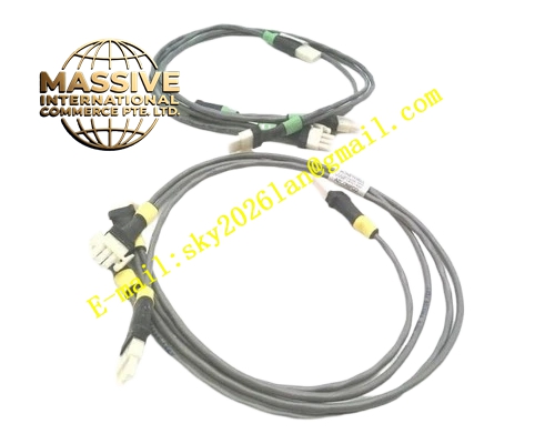
Description
Honeywell 51202329-102
Technical Specifications
- User control memory: 32 KB
- Connected I/O capacity: Up to 8 subracks, 512 I/O points
- Network interface: TDC LCN redundant control network
- Supply power: 5 V DC, ±15 V DC from backplane
- Operating temperature: 0 °C to +60 °C
- Control scan cycle: 100 ms typical
- Hot swap support: Online replacement for faulty processors
Functional Features Executes PID, logic and sequence control algorithms locally, independent of the central LCN supervisor. Schedules up to 8 remote I/O subracks over the local I/O bus. Redundant LCN network communication, automatic link switchover on failure. On-board LEDs indicate processor run, fault and network status. Non-volatile program memory, retains control logic without battery backup. Diagnostic fault reporting, locates faults to specific I/O subrack and channel.
Application Scenarios Process unit control for TDC3000 DCS systems Spare part replacement for failed I/O processors in existing TDC3000 plants Retrofit upgrade for legacy process manager units I/O expansion for existing TDC3000 control loops
Performance Parameters
- PID control loop capacity: 64 loops per processor
- Logic scan cycle: 10 ms
- Communication latency: ≤1 ms
- Mean time between failures: 500,000 hours
- Data retention: 10 years non-volatile
Material Composition FR4 high-speed PCB substrate 32-bit industrial processor chip Flash program memory Network communication chip Optocoupler isolation circuits Gold-plated backplane edge fingers
Structural Features Standard Eurocard dimensions, inserts into TDC3000 process manager slots. Front panel houses network status LEDs and fault indicator array. Metal shielded front panel contains high-speed processor electromagnetic radiation. Equal-length traces for redundant network signals, consistent signal delay. Anti-keying notch prevents insertion into non-processor slots.
Working Principle After power-up, the board loads the user control program from flash memory, entering cyclic scan mode. Each scan cycle reads I/O data from connected subracks, executes control logic and PID calculations, then writes output commands to the I/O subracks. Process data is transmitted over the LCN redundant network to the central operator station. The processor monitors internal health and connected subrack status; faults trigger local alarm and report to the operator station. Program and parameter data stored in non-volatile memory survives power cycles without re-download.
Installation Requirements Insert the processor board into the dedicated process manager slot, press evenly until gold fingers are fully seated. Connect I/O subrack expansion cables to front panel ports. Configure processor node address in the TDC3000 system software. Verify run LED activates, and all connected subracks are recognized after power-up.
Usage Notes Processor firmware version must match system software revision; mismatched versions prevent board recognition. Hot-swapping the processor causes connected I/O subracks to drop offline, triggering process alarms. Program download interrupts running control logic; perform during unit shutdown. Never install the processor in non-dedicated slots, incorrect slot causes backplane bus conflict.







