



Description
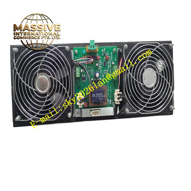
Honeywell 51303940-150
Technical Specifications Multiple analog output channels; 4-20mA current signal output; channel fault detection; short-circuit protection for each output; backplane communication with the DCS controller; status LED indicators on the front panel.
Functional Features Converts digital control commands from the controller into proportional 4-20mA current signals for field instruments. Maintains regulated current output even with normal loop resistance variation. Detects loop open and short-circuit conditions and reports faults to the control system. Supports safe preset value output when communication with the controller is lost. Isolates each output channel to limit cross-channel interference.
Application Scenarios Flow control valves, temperature regulating valves, pressure control loops, motor speed setpoint control and all continuous analog control loops in refining, chemical and power plant DCS systems.
Performance Parameters High output linearity across the full 4-20mA span; low temperature drift of output current; fast response to setpoint changes; stable current regulation under varying loop load resistance.
Material Composition Circuit board is FR-4 multilayer flame-retardant PCB; analog output drivers are precision industrial grade; backplane connector contacts are gold-plated; front panel has printed channel labels and status LEDs; internal power regulation components provide stable reference voltage.
Structural Characteristics Rack plug-in card form factor; front panel with multi-color LEDs for power, communication and channel fault status; rear gold finger connector for backplane connection; mechanical latches to lock the card in the rack slot.
Working Principle The DCS controller sends digital setpoint values to the module over the rack backplane. Onboard digital-to-analog converters translate digital values into precise current levels for each channel. Current regulation circuits maintain the required loop current regardless of normal wiring resistance changes. Continuous monitoring circuits detect abnormal loop conditions and trigger fault flags for the DCS system.
Installation Requirements Install the module into the designated slot of the Honeywell control rack. Wire each analog output loop to the matched field terminal assembly. Configure output range, fail-safe state and alarm limits in the DCS control configuration software. Calibrate each channel before placing control loops into automatic operation.
Precautions for Use Calculate total loop resistance to stay within the module’s compliance voltage limit. Do not connect high voltage sources directly to analog output terminals. Test the configured fail-safe state by interrupting controller communication.







