



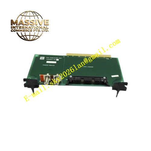
Description
Honeywell 51303947-100
Technical Specifications
- Backplane Interface: TDC 3000 proprietary backplane bus
- Signal Type: Mixed analog and digital signal routing
- Power Supply: 5VDC from rack backplane
- Operating Ambient Temperature: 0°C to +60°C
- Storage Temperature: -40°C to +85°C
- Relative Humidity: 5% to 90% RH non-condensing
- Mounting Method: Plug-in slot installation on TDC 3000 rack
- Certification: UL, CE, RoHS
Functional Features It routes field wiring signals to corresponding control logic modules through backplane bus. It provides built-in surge and transient voltage suppression for field signal lines. It isolates field side signal and rack logic circuit to reduce ground loop interference. It supports signal continuity detection and wiring breakage diagnosis. It transfers signal status data to main control board. It provides front panel LED indicators for channel fault and power status. It supports hot swap replacement without shutting down entire rack. It supports pre-wiring and rapid maintenance of field marshalling cables.
Application Scenarios TDC 3000 DCS marshalling cabinet signal distribution Petrochemical plant field sensor signal interface rack Refinery furnace and fractionation unit signal routing cabinet Power plant turbine auxiliary control signal marshalling Natural gas pipeline station TDC 3000 signal collection rack
Performance Parameters
- Mean Time Between Failures: 840000 hours
- Isolation Rating: 1500VAC between field signal and logic circuit
- Insulation Resistance: Greater than 1000 MΩ
- ESD Immunity: 8kV contact discharge
- Signal Bandwidth: Suitable for 4-20mA analog and dry contact digital signal
Material Composition FR4 flame retardant conformal coated multilayer PCB Signal isolation optocoupler components TVS surge suppression diodes and gas discharge tubes Signal routing copper trace array Gold plated edge connector for rack backplane Metal front panel with extraction handle and LED indicators Removable plastic terminal block for field wiring
Structural Features Standard TDC 3000 paddle card form factor. Front panel integrates removable terminal block and status LED indicators plus extraction handle. Rear gold plated edge connector connects to rack backplane bus. Internal PCB divides field signal zone and backplane logic zone with isolation barrier. Anti-key notch prevents reverse insertion into rack slot. Locking clip fixes module firmly after installation. Separate signal channels reduce cross-channel crosstalk.
Working Principle Field sensor and actuator wiring connects to terminal block on front panel. Signals pass through surge protection and isolation circuit on PCB. Valid signals are transmitted to backplane bus and forwarded to TDC 3000 control logic board. Control output commands from main board are routed back to field terminals through the same signal channel. Built-in diagnostic circuit continuously monitors signal line continuity and overvoltage status. Fault information is uploaded to main control board and operator station.
Installation Requirements Wear anti-static wrist strap before inserting module into TDC 3000 rack slot. Lock extraction handle after full insertion. Connect field shielded cable to terminal block and complete single point grounding for shield wire. Configure signal type and channel mapping in TDC 3000 engineering software. Power on rack and verify channel status LED. Check signal continuity with multimeter before putting into service. Separate low-level signal cable from high voltage power cable in wiring duct.
Usage Notes Do not apply voltage exceeding rated signal range to field terminals. Tighten terminal screws periodically under vibration environment. Replace module when surge protection components burn out. Keep terminal block clean and free from dust and corrosive gas. Do not use this card for high-power load signal directly.







