



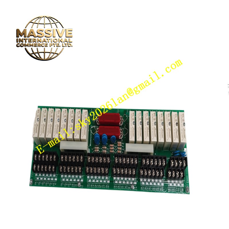
Description
Honeywell 51304441-275 MC-TDID52
Technical Specifications Multi-channel discrete signal termination; built-in transient voltage suppression; screw terminal connections for field wiring; compatible with MC series Honeywell digital input modules; cabinet DIN rail or backplate mounting.
Functional Features Offers labeled termination points for field limit switches, relay contacts and proximity sensors. Integrates suppression components to absorb voltage spikes induced on field discrete wiring. Provides channel grouping and isolation for maintenance loop disconnection. Transmits conditioned discrete signals to the matched digital input module via dedicated interconnection wiring. Supports shield connection points for field cable shielding.
Application Scenarios Process interlock cabinets, motor control center discrete feedback wiring, safety valve limit switch monitoring and general discrete I/O cabinets for Honeywell DCS platforms.
Performance Parameters Low contact resistance at screw terminals; fast transient suppression response; consistent electrical characteristics for all signal channels; long-term stability in industrial cabinet environments.
Material Composition Base housing is flame-retardant thermoplastic; terminal screws and contact springs are nickel-plated copper; suppression components are industrial semiconductor devices; mounting hardware is coated steel.
Structural Characteristics Modular terminal strip assembly with grouped channel positions; printed terminal function labels on the housing surface; dedicated points for cable shield termination; mounting slots for DIN rail installation inside electrical cabinets.
Working Principle Field discrete device cables terminate at the screw terminals of the assembly. Signal lines pass through transient suppression components before connecting to the digital input module. The suppression components clamp abnormal voltage spikes before they can reach the sensitive input circuitry of the I/O card. Normal contact state signals pass through to the module without alteration.
Installation Requirements Mount the terminal assembly securely inside the control cabinet. Connect field discrete cables to the corresponding labeled terminals. Run the interconnection cable between this terminal block and the matched digital input module. Apply single-point shield grounding for all field sensor cables.
Precautions for Use Confirm field contact voltage matches the module input rating before wiring. Do not use this terminal assembly for power distribution circuits. Retain spare terminal capacity for future instrument additions.







