



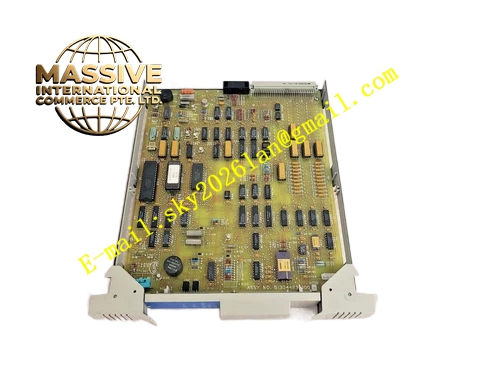
Description
Honeywell 51304489-100
Technical Specifications
- Channel Quantity: 32 digital output channels
- Output Type: 24 VDC sinking transistor output
- Single Channel Rated Continuous Current: 0.5 A
- Peak Surge Current: 2 A per channel
- Group Isolation: 2500 VAC reinforced optical isolation
- Backplane Bus: HPM I/O backplane
- Communication Bus: UCN universal control network
- Operating Temperature: 0 °C to +60 °C
- Maximum Power Consumption: 9 W under full rated load
- Hot Swap Support: Yes
Functional Features Independent electronic current limiting and short circuit latch protection for every channel. Output readback circuit compares actual terminal state against commanded state to detect load failure. Front panel LED array shows module power, network communication and group fault status. Command message uses CRC checksum to reject corrupted UCN frames. Output state hold function retains last state when UCN communication is lost. Group fault alarm can be mapped to DCS event sequence log for SOE recording.
Application Scenarios Solenoid valve on-off control for process isolation valves Local alarm horn and warning light drive in chemical process area Auxiliary relay coil control for pump and fan interlock circuit Batch sequence control discrete output expansion TDC3000 HPM rack digital output spare replacement
Performance Parameters
- Turn-on and turn-off switching time: ≤ 1 ms
- Short circuit hardware shutdown response: < 2 µs
- Isolation withstand voltage: 2500 VAC for 60 seconds
- Channel crosstalk: -60 dB minimum
- Fault reporting latency: Less than 120 ms
Material Composition Multilayer FR4 UL94 V0 PCB, N-channel power MOSFET switches, high grade optocoupler isolators, current sampling precision resistors, TVS surge suppression diodes, X7R decoupling capacitors, gold plated backplane edge connector, flame retardant plastic front panel with extraction handle.
Structural Features Standard plug-in eurocard form factor matching HPM rack slot dimension. Front panel LED indicators separate module health status and group fault signals. Rear edge connector connects to HPM backplane bus. Internal metal isolation partition separates low voltage logic zone and field power zone. Anti-keying notch on card edge prevents reversed insertion into incompatible slot. Component layout balances thermal distribution for full load operation.
Working Principle HPM controller transmits digital output command over UCN bus and backplane. Onboard logic chip verifies CRC checksum and drives optocoupler isolation stage to activate MOSFET output switch. Sampling resistor continuously monitors channel load current. Overcurrent condition triggers hardware latch shutdown and fault flag upload. When UCN communication is interrupted, all channels freeze at last commanded state.
Installation Requirements Inductive field loads must install freewheeling diode directly across load terminals. Field output wiring uses twisted pair cable and runs separately from analog signal cable. Confirm HPM firmware compatibility before module installation. Tighten paired FTA terminal screws to specified torque value. Run module self-test function in HPM configuration software after replacement.
Usage Notes Short circuit fault locks channel off; rack power cycle clears latch only after field fault repair. Single channel load current cannot exceed 0.5 A continuous rating. Do not connect AC voltage load directly to 24 VDC output channels. Internal circuit modification and component replacement is forbidden.







