



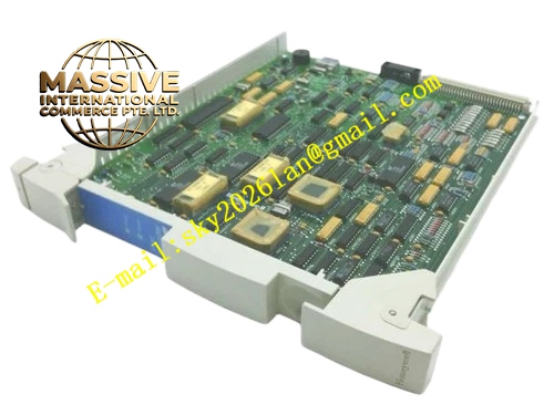
Description
Honeywell 51304516-250
Technical Specifications
- Supported Field Signal: 4 mA to 20 mA analog + superimposed HART digital signal
- Communication Protocol: HART revision 5, 6 and 7
- Channel Quantity: Multi-channel HART interface group
- Isolation Rating: 500 VAC group reinforced isolation
- Backplane Interface: HPM I/O backplane bus
- Operating Temperature: -10 °C to +65 °C
- Power Supply: 24 VDC field loop power, 5 VDC rack logic power
- Form Factor: Standard HPM plug-in rack card
- Hot Swap Support: Yes
Functional Features Simultaneous acquisition of analog 4-20mA value and multi-variable HART digital signal. HART command forwarding supports device calibration, tag edit and extended diagnostic reading. Enhanced surge protection circuit suppresses larger transient voltage spike on long field cable. Per channel loop break, under-range, over-range and HART device malfunction diagnostic. Front panel LED indicates module power, HART transmit/receive activity and channel fault. CRC checksum validates all inbound and outbound communication frames. Supports HART burst mode and multi-drop network topology.
Application Scenarios Outdoor long distance HART transmitter connection to TDC3000 DCS HART revision 7 multi-variable flow transmitter integration Smart positioner online diagnostic and calibration control HPM rack old HART interface module upgrade replacement Offshore platform and coastal chemical plant intelligent instrument monitoring
Performance Parameters
- HART baud rate: 1200 bps fixed
- Analog measurement accuracy: ±0.1 % full scale
- HART communication response timeout: Configurable from 200 ms to 1000 ms
- Isolation withstand voltage: 500 VAC for 60 seconds
- Channel crosstalk: -62 dB minimum
- Surge withstand capacity improved 40 % compared with revision 200
Material Composition FR4 multilayer PCB, upgraded HART modem IC, low drift instrumentation amplifier, high grade optocoupler isolation chips, precision 250 ohm shunt resistors, high power TVS surge diodes, screw terminal FTA interface, gold plated backplane edge connector, flame retardant plastic front panel.
Structural Features Identical plug-in eurocard form factor with 51304516-200. Rear gold edge connector mates with HPM backplane bus. Internal isolation barrier separates field HART loop circuit and rack logic circuit. Front panel LED array shows power, TX/RX activity and group fault status. Anti-keying notch prevents reversed insertion. Upgraded surge components are placed near field terminal connector.
Working Principle Field 4-20 mA current flows through precision shunt resistor and converts to analog voltage for ADC sampling. Superimposed HART FSK signal is demodulated by upgraded modem chip which supports HART 7 extended command set. Modem parses multi-variable response data. Valid digital variable and analog value are packed into communication frame and transmitted to HPM controller. Enhanced surge circuit suppresses transient spike before signal enters modem stage. Abnormal loop impedance or missing HART response triggers channel fault flag.
Installation Requirements Field HART wiring uses twisted shielded pair cable, shield grounded only at cabinet side. Install 250 ohm HART load resistor on field loop for point-to-point connection. Separate HART signal cable from high voltage power cable. Configure transmitter tag, polling address and multi-drop mode in HPM configuration software. This revision can directly replace 51304516-200 without rack wiring modification.
Usage Notes Dual end shield grounding creates HART communication noise and packet loss. Do not apply AC voltage directly to 4-20 mA HART terminals. HART multi-drop loop must respect maximum unit count and total loop resistance limit. Do not replace onboard shunt resistor and surge components.







