



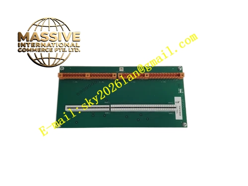
Description
Honeywell 51304525-100
Technical Specifications
- Channel Count: 16 independent supervised digital input channels
- Input Signal Type: Dry contact with end-of-line supervision resistor
- Backplane Interface: TDC3000 proprietary backplane bus
- Power Supply: 5VDC and 24VDC from rack backplane
- Operating Ambient Temperature: 0°C to +60°C
- Storage Temperature: -40°C to +85°C
- Relative Humidity: 5% to 90% RH non-condensing
- Mounting Type: Plug-in slot installation on TDC3000 rack
- Certification: UL, CE, RoHS
- Supervision Resistor Value: 1kΩ
Functional Features It cyclically samples 16 supervised digital input channels. It distinguishes three status for each channel: contact closed, contact open and wiring fault. It detects wire breakage, short circuit and missing end-of-line resistor fault. It supports configurable input debounce time to filter transient contact bounce signal. It carries built-in overvoltage and reverse polarity protection for each channel. It uploads channel status and wiring fault information to TDC3000 main processor. It carries front panel LED indicators for power, run status and fault. It supports hot swap replacement in redundant rack configuration. It stores debounce parameter configuration in non-volatile memory. It supports interlock signal time stamp recording.
Application Scenarios Petrochemical plant emergency shutdown system signal collection rack Refinery burner management safety interlock input cabinet Chemical plant high-risk reactor emergency stop signal monitoring Power plant boiler safety interlock discrete signal rack Natural gas plant compressor emergency shutdown supervised input
Performance Parameters
- Input Debounce Time: Configurable from 1ms to 1000ms
- Mean Time Between Failures: 820000 hours
- Isolation Rating: 1500VAC channel to system isolation
- Insulation Resistance: Greater than 1000 MΩ
- ESD Immunity: 8kV contact discharge
Material Composition FR4 flame retardant conformal coated multilayer PCB Supervision current source circuit array Digital input optocoupler isolation array Input protection diode and current limiting resistor network Backplane bus transceiver chip Watchdog monitoring circuit Gold plated edge connector for TDC3000 backplane Metal front panel with extraction handle and LED indicators Removable plastic terminal block for field wiring
Structural Features Standard TDC3000 paddle card form factor. Front panel integrates removable field wiring terminal block and grouped LED indicators plus extraction handle. Rear gold plated edge connector mates with rack backplane power and control bus. Every supervised input channel has independent optocoupler isolation and supervision current circuit. Anti-key notch prevents reverse insertion into rack slot. Locking clip secures module firmly after installation. Conformal coating fully covers PCB surface to resist dust, moisture and corrosive gas in safety cabinet environment.
Working Principle On-board supervision current source sends constant current to field contact loop with end-of-line resistor. When contact closes, current bypasses supervision resistor and optocoupler turns on. When contact opens, current passes through supervision resistor and optocoupler receives reduced current. When wire breaks or short circuit occurs, supervision current deviates from normal range and fault flag generates. Internal logic circuit scans all channels in fixed cycle and packages status data to TDC3000 main processor via backplane bus. Debounce circuit filters transient bounce signal. Fault information is uploaded to operator station.
Installation Requirements Wear anti-static wrist strap before inserting module into vacant rack slot. Lock extraction handle after full seating. Connect field dry contact wiring and install 1kΩ end-of-line supervision resistor at field terminal. Configure input debounce time and point description in engineering software. Power on rack and verify run LED steady on. Test each channel status by forcing contact open, close and wiring fault. Separate supervised input cable from analog signal cable in wiring duct.
Usage Notes Install matching end-of-line supervision resistor for every field loop. Do not apply voltage higher than 30VDC to input terminals. Check terminal screw tightness periodically under vibration environment. Clean terminal block when conductive dust accumulates. Do not remove conformal coating on PCB surface. Replace module when multiple channels show consistent supervision failure.







