



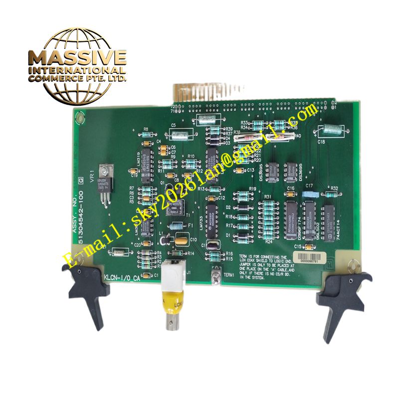
Description
Honeywell 51304542-100
Technical Specifications Multiple module slot positions; integrated power distribution traces; high-speed parallel control bus traces; gold-plated slot connectors; metal support frame; defined maximum rack power rating.
Functional Features Provides mechanical mounting positions for all compatible Honeywell rack modules. Distributes regulated DC power from the power supply modules to every slot connector. Transfers high-speed control bus data between the controller, communication cards and I/O modules. Maintains stable electrical contact for hot-swap capable modules. Provides dedicated grounding points for rack protective earth connections.
Application Scenarios Honeywell Experion PKS main controller racks, redundant control cabinets, process automation DCS rooms and industrial control building central control equipment.
Performance Parameters Controlled impedance for high-speed bus signals; low voltage drop on power distribution traces; consistent connector contact resistance across all slots; mechanical rigidity under cabinet vibration.
Material Composition Backplane circuit substrate is thick high-current FR-4 multilayer PCB; slot connector pins are gold-plated copper alloy; structural support frame is powder-coated steel; grounding bus bars are tin-plated copper.
Structural Characteristics Rectangular metal frame with horizontally arranged card slots; large printed circuit backplane mounted to the rear of the frame; each slot contains a multi-pin connector for module gold fingers; dedicated grounding terminals at the chassis edge.
Working Principle Power supply modules feed DC power onto the backplane power traces. The controller communicates with I/O and communication modules via differential bus traces routed on the backplane PCB. Each module draws operating power and exchanges data through its slot connector. The metal frame and dedicated ground traces maintain protective earth bonding for the entire rack assembly.
Installation Requirements Mount the chassis to the cabinet backplate using the provided mounting hardware. Complete protective earth wiring to the designated ground terminals. Insert modules only into their assigned slot locations defined in Honeywell system drawings. Inspect connector pins for damage before module installation.
Precautions for Use Do not apply power to the chassis with damaged or bent connector pins. Keep the rack internal area free of metal debris and conductive dust. Do not modify or cut any traces on the backplane PCB.







