



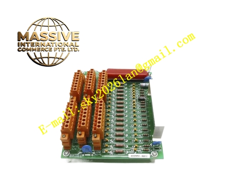
Description
Honeywell 51304544-100
Technical Specifications
- Channel Count: 8 independent thermocouple input channels
- Supported Thermocouple Types: K, J, T, E, S, R, B
- Backplane Interface: TDC3000 proprietary backplane bus
- Power Supply: 5VDC and 12VDC from rack backplane
- Operating Ambient Temperature: 0°C to +60°C
- Storage Temperature: -40°C to +85°C
- Relative Humidity: 5% to 90% RH non-condensing
- Mounting Type: Plug-in slot installation on TDC3000 control rack
- Certification: UL, CE, RoHS
- Cold Junction Compensation Range: -20°C to +60°C
Functional Features It cyclically samples millivolt thermoelectric signal from each thermocouple channel. It executes real-time cold junction compensation using on-board temperature sensor. It converts millivolt signal into temperature value according to thermocouple standard curve. It supports configurable digital filtering and temperature alarm threshold. It detects sensor open circuit, wire breakage and signal out-of-range fault. It uploads raw millivolt value and converted temperature value to TDC3000 main processor. It carries front panel LED indicators for power, run status and channel fault. It supports hot swap replacement under redundant rack configuration. It stores thermocouple type and calibration parameters in non-volatile memory. It supports single-channel calibration operation from engineering workstation.
Application Scenarios Petrochemical plant furnace high-temperature measurement rack Refinery reforming and cracking furnace temperature signal cabinet Chemical plant high-temperature reactor temperature monitoring rack Power plant boiler furnace and flue gas temperature collection Metallurgical process high-temperature thermocouple signal acquisition
Performance Parameters
- ADC Resolution: 16-bit
- Temperature Accuracy: ±0.2°C for K type thermocouple within 0°C to 600°C
- Mean Time Between Failures: 790000 hours
- Channel Isolation Rating: 1500VAC between field channel and internal logic circuit
- ESD Immunity: 8kV contact discharge
- Sampling Period: Configurable from 50ms to 1000ms
Material Composition FR4 flame retardant conformal coated multilayer PCB High precision low-drift amplifier array for weak millivolt signal 16-bit ADC conversion chip On-board cold junction temperature sensor Optocoupler isolation components TVS surge suppression diodes Backplane bus transceiver chip Gold plated edge connector for TDC3000 backplane Metal front panel with extraction handle and LED indicators Removable plastic terminal block for thermocouple wiring
Structural Features Standard TDC3000 paddle card form factor. Front panel integrates removable field wiring terminal block and grouped LED indicators plus extraction handle. Rear gold plated edge connector mates with rack backplane power and control bus. Each thermocouple channel adopts independent low-noise amplification and isolation circuit. Cold junction temperature sensor is placed close to terminal block to guarantee compensation accuracy. Anti-key notch prevents reverse insertion into rack slot. Locking clip secures module firmly after installation. Internal PCB layout strictly separates weak millivolt analog circuit and digital bus circuit to reduce noise and thermal drift. Conformal coating fully covers PCB surface to resist dust and corrosive gas.
Working Principle Thermocouple generates millivolt thermoelectric voltage corresponding to temperature difference between measuring end and cold junction. Weak millivolt signal enters low-noise amplifier circuit for signal amplification. Cold junction sensor measures terminal block temperature and sends compensation value to logic chip. ADC chip converts amplified analog signal into digital value. On-board logic chip calculates final temperature value with cold junction compensation and thermocouple curve conversion. Processed temperature data is packaged and transmitted to TDC3000 main processor via backplane bus. Diagnostic circuit monitors signal amplitude continuously. If sensor open circuit is detected, fault flag generates and alarm uploads to operator station.
Installation Requirements Wear anti-static wrist strap before inserting module into vacant rack slot. Lock extraction handle after full seating. Connect dedicated thermocouple extension wire to corresponding channel terminals. Configure thermocouple type, temperature range and filter parameter in engineering software. Power on rack and verify run LED steady on. Perform channel calibration with standard millivolt signal source before commissioning. Separate thermocouple extension cable from high voltage power cable in wiring duct.
Usage Notes Use dedicated thermocouple extension wire matching sensor type strictly. Do not use ordinary copper wire for thermocouple signal wiring. Keep shield wire single point grounding at marshalling cabinet side. Check terminal screw tightness periodically under vibration environment. Recalibrate each channel every 12 months. Replace module when multiple channels show abnormal temperature reading.







