



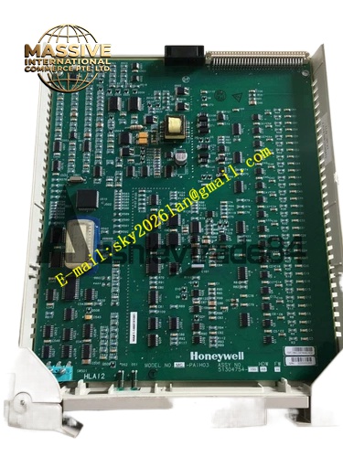
Description
Honeywell 51304754-150
Technical Specifications
- Input power: 24 V DC main supply
- Output branches: 5 V DC logic supply, ±15 V DC analog supply, 24 V DC field supply
- Per-branch rated current: 15 A for 5 V, 3 A for ±15 V, 10 A for 24 V
- Protection element: Resettable electronic fuse per branch
- Backplane interface: Direct connection to subrack power bus
- Operating temperature: 0 °C to +60 °C
Functional Features Multiple voltage outputs, supplies all required rails for mixed analog and digital I/O cards. Per-branch electronic resettable fuses, branch short circuit does not disrupt remaining rack power. On-board EMI filter, removes high-frequency noise from incoming supply. On-board LEDs indicate power normal status for each voltage rail. Power hold-up time 20 ms, no output disturbance during short supply dips. Mounts at the subrack end, no additional rack space required.
Application Scenarios Power distribution for TDC3000 I/O subracks Spare part replacement for power board faults causing card dropout Rack power upgrade for increased I/O point count New TDC3000 subrack assembly power interface
Performance Parameters
- Output voltage regulation: ±2%
- Power conversion efficiency: 90% at full load
- Output ripple: ≤50 mV peak to peak
- Surge protection: ±6 kV contact ESD
- Branch fault response: ≤10 ms
Material Composition FR4 high-current PCB substrate DC-DC regulator modules Electronic resettable fuse array EMI filter inductor and capacitor bank Status LEDs Metal mounting bracket
Structural Features Long rectangular board form factor, mounts at the subrack end slot. Front panel houses power switch, branch LEDs and fault alarm contacts. Wide copper traces for high-current power paths. Metal bracket locks to subrack end uprights.
Working Principle Incoming 24 V DC supply connects to the distribution board. The on-board DC-DC regulators convert 24 V to regulated 5 V, +15 V and -15 V outputs. EMI filters remove high-frequency noise on all output rails. Per-branch electronic fuses monitor output current; branch short circuit triggers automatic current limiting, cutting power to the affected branch. Output LEDs illuminate to indicate live voltage on each rail. Regulated power routes to the subrack backplane, distributing to all installed I/O cards.
Installation Requirements Mount the board in the dedicated end slot of the I/O subrack. Connect 24 V DC supply to input terminals, observe correct polarity. Check all branch LEDs after power-up, confirm all voltage rails are active. Connect fault alarm contacts to the subrack monitoring system.
Usage Notes Total rack load current must not exceed branch ratings; overloading triggers over-temperature protection. Never block power board ventilation with cabling; poor ventilation shortens regulator life. Resetting a tripped electronic fuse requires removing the short circuit fault first, repeated reset attempts damage the regulator. Never short-circuit output terminals; short circuit instantly destroys the DC-DC regulator modules.







