



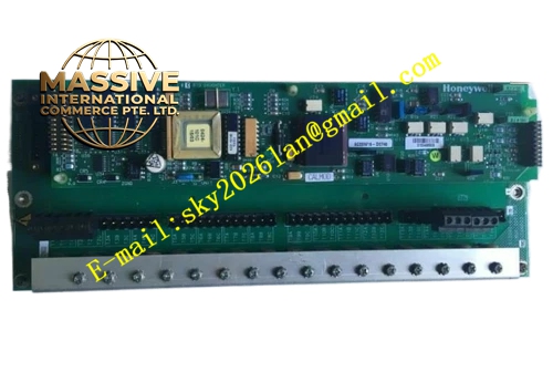
Description
Honeywell 51309218-175
Technical Specifications DCS rack plug-in communication board; Serial field communication interface; Onboard protocol processing chip; Operating temperature 0°C to +60°C; 5V DC backplane power supply; Onboard memory buffer; Front panel LED status indicators.
Functional Features Independent serial protocol processing reduces main controller load; Transmits real-time I/O data between DCS and remote field equipment; Captures communication error and reports fault status; Data buffer stores transmission data during transient disturbance; LED indicators display power, transmit, receive and fault state; Supports configuration of communication parameters via DCS workstation.
Application Scenarios Large petrochemical DCS control cabinet; Chemical plant remote I/O communication rack; Power station DCS communication subsystem; Oil pipeline control system; Fertilizer plant process control network; Mining process monitoring DCS system.
Performance Parameters Serial communication baud rate stable; Data frame transmission integrity maintained; Communication error detection reliable; Backplane data exchange timing consistent; Circuit anti-interference capability meets industrial DCS specification.
Material Composition FR4 multi-layer flame retardant PCB; Gold plated backplane edge connector; Communication microprocessor; Serial transceiver chip; SRAM memory buffer; LED indicators; Metal front panel with locking mechanism.
Structural Features Rack plug-in card design; Rear gold plated edge connector mates with DCS backplane; Front metal panel with status LEDs and communication port; Card locking latch on front panel; Internal metal shield covers high speed digital circuit area.
Working Principle The board connects with DCS controller through rack backplane. Onboard microprocessor executes serial communication protocol. It receives process output commands from DCS controller, packages data and sends to remote field devices via serial port. It receives input data from field equipment and transmits data to DCS controller through backplane. The board continuously monitors communication frame quality and logs communication fault events.
Installation Requirements Insert communication board into empty DCS rack slot and lock latch; Connect serial field communication cable to front port; Configure communication baud rate, address and protocol in DCS configuration software; Verify rack power supply load; Use shielded cable for field serial wiring.
Precautions for Use Implement electrostatic protection before handling PCB card; Do not insert or remove card during rack power on without hot-swap authorization; Keep communication cable away from high voltage power lines; Save DCS communication configuration before board replacement; Inspect LED status during routine maintenance.







