



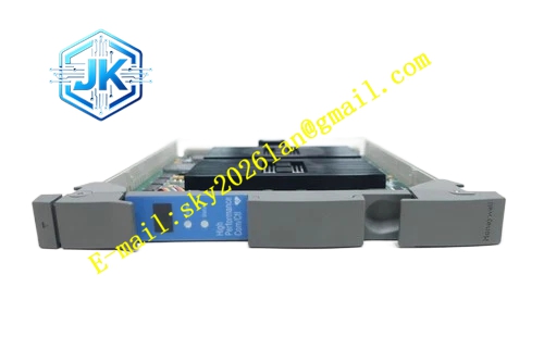
Description
Honeywell 51400869-100
Technical Specifications Channel Count: 8 relay output channels Contact Type: Form A dry contact Maximum Contact Rating: 240V AC / 2A, 120V DC / 0.5A Power Supply: 5V DC for logic circuit Power Consumption: 6.8W Operating Temperature Range: 0℃ to 60℃ Storage Temperature Range: -40℃ to 85℃ Isolation Withstand Voltage: 1500V AC per channel Relative Humidity: 5% to 95%, non-condensing
Functional Features It provides independent electrical isolation between each relay channel and internal logic circuit. It supports configurable fail-safe state including keep last state or de-energized contact. It carries out relay coil fault detection and contact feedback monitoring. It supports hot swap operation. It stores channel fail-safe configuration and fault threshold parameters in non-volatile memory. It uploads relay action status and channel fault information to the DCS diagnostic system. It integrates surge suppression components for contact terminals.
Application Scenarios On-off control of solenoid valves and shut-off valves in pipeline interlock systems. Start-stop command output for auxiliary pumps, fans and agitators. Sequence control output for batch process and automatic loading systems. Replacement and spare stocking for aging relay output cards in legacy TPS UCN racks.
Performance Parameters Relay Operating Time: ≤10ms Contact Mechanical Life: ≥10 million switching cycles Contact Electrical Life: ≥100,000 cycles under rated load Channel Response Time: ≤15ms
Material Composition PCB Substrate: High-TG flame-retardant FR-4 multi-layer glass fiber board Industrial grade sealed electromagnetic relay components Optocoupler isolation chips Surge absorption and freewheeling diode components Gold-plated back edge fingers Gold-plated field terminal contacts Cold-rolled steel front panel with electrostatic spray coating
Structural Features Standard European pluggable card structure, installed in dedicated digital output slot of UCN rack. Front panel is equipped with run indicator light, fault indicator light and individual channel status indicator lights. Field wiring terminals are arranged on the side panel for load circuit wiring. Each relay channel adopts independent isolation zone to prevent fault cross spread between channels. Relay components reserve heat dissipation gap to reduce thermal aging speed.
Working Principle The module receives digital on-off commands from IOP processor through backplane bus. The logic chip sends drive signal to the corresponding relay coil. The electromagnetic relay pulls in or releases the contact to complete the switching of field load circuit. The feedback circuit samples contact state in real time and compares the actual state with command state. When coil damage or contact sticking fault occurs, the module triggers alarm and executes pre-configured fail-safe action. It uploads relay status and fault tags to the rack IOP processor.
Installation Requirements Insert the module vertically into the dedicated digital output slot of UCN rack and tighten fixing screws. Connect field load wires to relay contact terminals strictly within rated electrical range. Confirm the load current and voltage do not exceed contact rating before power on. Download channel fail-safe mode configuration from Control Builder software. Verify relay action and fault detection function on the HPM diagnostic screen.
Precautions Release static electricity before plugging the module to protect logic and isolation chips. Inductive loads such as solenoid valves must be equipped with external surge absorption devices. Long-term overload use accelerates relay contact ablation and reduces service life. Do not short-circuit output terminals, which causes permanent damage to relay drive circuit. Regular inspection of contact aging status is required for high-frequency switching channels.







