



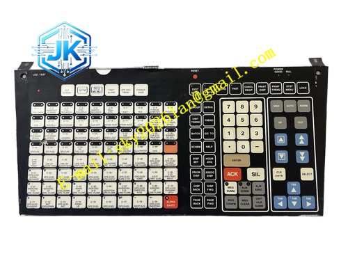
Description
Honeywell 51401560-100
Technical Specifications Channel Count: 16 analog signal channels Supported Signal Type: 4-20mA DC, RTD resistance signal, thermocouple millivolt signal Per-channel Fuse Rating: 0.25A Surge Withstand Capacity: 1kV 1.2/50μs surge per channel Loop Power: 24V DC for current loop Power Consumption: 4.8W Operating Temperature Range: 0℃ to 60℃ Storage Temperature Range: -40℃ to 85℃ Isolation Withstand Voltage: 1500V AC Relative Humidity: 5% to 95%, non-condensing
Functional Features It integrates independent fast blow fuse and TVS transient suppression diode for each channel. It supports wiring supervision and loop open circuit detection for field return lines. It carries out signal level matching between field instruments and UCN analog processor cards. It supports hot swap operation when paired with compatible analog processor card. It stores channel supervision configuration in non-volatile memory. It uploads fuse blown alarm and channel wiring fault status to the DCS diagnostic system. It provides common return grouping for field wiring marshalling.
Application Scenarios Field termination interface for pressure, flow and level 4-20mA transmitter signal loops. Marshalling cabinet signal distribution for RTD and thermocouple temperature measurement loops. Auxiliary termination for analog signal loops in ESD and interlock control systems. Replacement and spare stocking for aging analog FTA cards in legacy TPS UCN marshalling cabinets.
Performance Parameters Signal Transmission Delay: ≤0.8ms Fuse Fault Detection Resolution: 0.05mA Channel Isolation Resistance: ≥1000MΩ
Material Composition PCB Substrate: High-TG flame-retardant FR-4 multi-layer glass fiber board Fast blow miniature fuse components TVS transient suppression diodes Signal buffer and protection chips Gold-plated back edge fingers Gold-plated field terminal block contacts Cold-rolled steel front panel with electrostatic spray coating
Structural Features Standard European pluggable card structure, installed in dedicated FTA slot of UCN marshalling rack. Front panel is equipped with run indicator light, fuse fault indicator light and group channel status indicator lights. Two groups of terminal blocks are arranged on the side panel, one for field instrument wiring and one for ribbon cable connection to analog processor card. Each channel fuse adopts replaceable structure for convenient on-site maintenance. Protection components are arranged close to field terminals to suppress incoming surge at the entry point.
Working Principle Field analog signals from transmitters or temperature sensors enter the module through marshalling terminals. Each channel passes through fuse and surge suppression circuit to absorb transient voltage spikes. The signal buffer circuit shapes analog signal and transmits the signal to the matched analog processor card via ribbon cable. The supervision circuit continuously monitors loop current and impedance. When fuse blows or field wire breaks, the module generates fault signal and uploads alarm information to the rack IOP processor.
Installation Requirements Insert the module vertically into the dedicated FTA slot of UCN marshalling rack and tighten fixing screws. Connect field instrument wiring to field terminals and ribbon cable to the analog processor card side terminals. Use specified ribbon cable to connect this FTA module with corresponding analog processor card. Download channel supervision configuration parameters from Control Builder software after power on. Verify signal transmission and fuse fault alarm function on the HPM diagnostic screen.
Precautions Release static electricity before plugging the module to protect buffer and protection chips. Only replace fuse with the same rated current, higher rating fuse loses protection capability. Do not connect AC voltage signals to this module terminals. Check ribbon cable connection firmly, loose cable causes signal loss and intermittent fault. This module must be used together with matching UCN analog processor card, it cannot work independently.







