



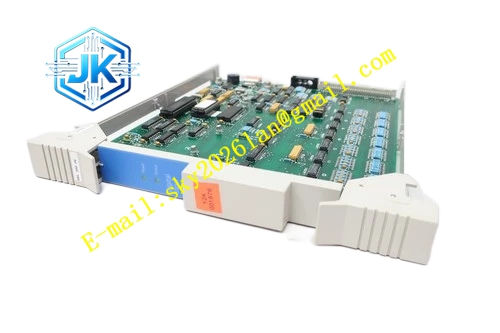
Description
Honeywell 51401569-100
Technical Specifications Bus Interface: LCN coaxial bus, BNC connectors Nominal Impedance: 50Ω Working Bandwidth: 5Mbps LCN signal bandwidth Power Supply: 5V DC Power Consumption: 3.6W Operating Temperature Range: 0℃ to 60℃ Storage Temperature Range: -40℃ to 85℃ Isolation Withstand Voltage: 1500V AC Relative Humidity: 5% to 95%, non-condensing
Functional Features It provides high-precision impedance termination for the end of LCN trunk bus to eliminate signal reflection. It integrates low-pass filter circuit to suppress high-frequency industrial noise and spike interference. It continuously samples the bus signal amplitude and sends signal strength data to the LCN diagnostic system. It detects open circuit and short-circuit fault of the trunk terminal and uploads alarm. It supports hot swap operation. It isolates the terminal circuit from the main trunk to avoid component failure causing bus short circuit. It improves the stability of long-distance LCN trunk transmission.
Application Scenarios Terminal impedance matching and signal filtering for the two physical ends of main LCN trunk bus. Signal quality monitoring of long-distance LCN trunk lines in large-scale TPS systems. Replacement of aging terminal resistors and signal conditioning units. Noise suppression for LCN bus near high-power motor and frequency converter workshops.
Performance Parameters Termination Impedance Accuracy: 50Ω ±0.5Ω Noise Suppression Attenuation: ≥30dB for frequency above 10MHz Signal Monitoring Resolution: 0.01V Return Loss: ≥25dB
Material Composition PCB Substrate: Low-loss high-frequency FR-4 board with RF impedance control layout Precision non-inductive termination resistor LC low-pass filter network Signal sampling and conditioning chip Gold-plated BNC coaxial connectors Metal shielding shell Anti-static coated front panel
Structural Features Standard European pluggable card structure, suitable for dedicated LCN terminal slot. Front panel is equipped with run indicator light and bus signal strength indicator light. Two BNC connectors are arranged on the side for trunk bus series connection. The whole RF circuit area is wrapped by metal shielding shell to avoid external noise coupling. All passive components adopt high-frequency low-temperature drift type.
Working Principle The LCN trunk bus signal enters the module through the BNC port. The internal precision termination resistor matches the characteristic impedance of the coaxial cable to absorb reflected signal. The low-pass filter circuit filters high-frequency noise superimposed on the LCN signal. The sampling circuit collects the real-time signal amplitude of the trunk bus and transmits monitoring data to the LCN diagnostic module. When the trunk cable is open or shorted, the sampling circuit detects abnormal signal and triggers alarm output.
Installation Requirements Insert the module vertically into the dedicated slot and tighten fixing screws. Install the module at the two physical terminal positions of the main LCN trunk bus. Connect the trunk coaxial cable to the input BNC port of the module. Check the bus signal amplitude and return loss value on the LCN diagnostic screen after power on. Keep the module away from high-power electrical equipment and heat sources.
Precautions Two termination modules must be installed at the two ends of one complete LCN trunk bus, and no extra termination modules shall be added on the middle branch. Release static electricity before touching the internal RF circuit. The internal precision resistor cannot be replaced with ordinary power resistor, which will cause impedance mismatch. Dust and moisture on BNC connectors will affect signal quality. This module is only designed for LCN bus and cannot be used for UCN bus termination.







