



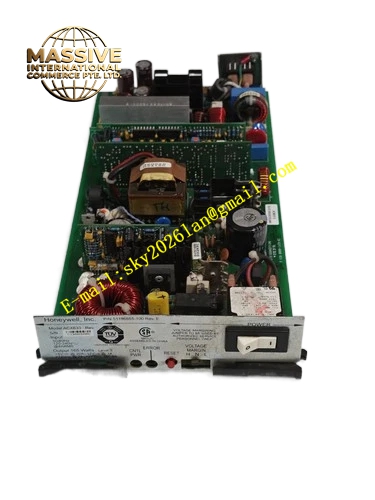
Description
Honeywell 51402455-100 MP-DNCF02-201
Technical Specifications Dual brushless axial fans; rack backplane 24VDC supply; built-in NTC temperature sensor; multi-speed PWM fan control; independent tachometer feedback per fan; operating temperature 0℃ to 60℃; storage temperature -40℃ to 85℃; humidity 5% to 95% non-condensing; fan fault detection; mechanical footprint identical to revision 200.
Functional Features It adjusts fan speed according to measured rack internal temperature. At low temperature the fans run slowly to reduce noise and extend bearing life. As temperature rises, fan speed ramps up to increase cooling airflow. It still reports individual fan stall and low speed faults. It drops into full speed mode under over-temperature condition. The assembly is backward compatible as a direct replacement for revision 200.
Application Scenarios Upgrade replacement for aging MP-DNCF02-200 fan assemblies in TDC3000 racks; noise sensitive control room installations; energy saving retrofit for continuous process plant control cabinets; dual node rack cooling in HVAC conditioned TPS environments.
Performance Parameters Speed range spans low noise low RPM to full rated airflow; NTC response matches rack thermal time constant; fan MTBF is improved over the constant speed 200 revision; diagnostic output is fully compatible with TPS node firmware.
Material Composition Fan frames and impellers use flame retardant reinforced engineering plastic; brushless DC fan motors; temperature monitoring PCB with NTC thermistor; slide rail housing of reinforced plastic.
Structural Characteristics Identical slide-in drawer form factor to revision 200; front panel has power and fault LEDs; rear backplane connector is pin compatible; NTC sensor is mounted in the hot air exhaust stream.
Working Principle The monitor PCB reads the NTC thermistor located in the rack exhaust air. The controller compares measured temperature against preset thresholds and outputs PWM drive signals to both fans. At low temperature the fans run at minimum speed. As rack heat load increases the fans speed up. Tachometer signals from each fan are monitored continuously; any fan anomaly triggers a fault signal to the node processor.
Installation Requirements Slide the assembly into the TDC3000 fan slot; ensure the NTC sensor is exposed to the exhaust air stream and not blocked by cable bundles. Confirm rear backplane connector fully seats. Maintain clean cabinet air filters. This assembly directly replaces revision 200 without rack modification.
Usage Notes Do not cover or insulate the NTC sensor, otherwise fan speed control will be inaccurate. Keep the air filters clean to avoid false over-temperature trip. During maintenance, complete the replacement promptly because forced cooling is interrupted. This revision requires matching node firmware that supports the new fan control feature.







