



Description
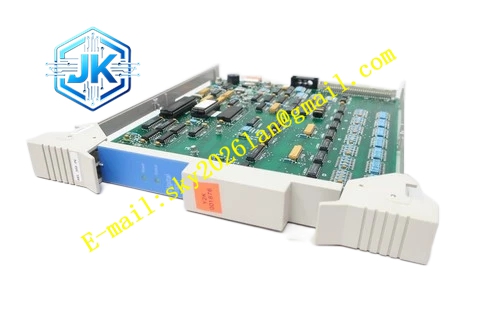
Honeywell 51402615-400
Technical Specifications Bus Interface: Dual redundant LCN coaxial bus, BNC connectors Communication Rate: 5Mbps Backplane Interface: Node local parallel backplane bus Power Supply: 5V DC Power Consumption: 9.5W Operating Temperature Range: 0℃ to 65℃ Storage Temperature Range: -40℃ to 85℃ Isolation Withstand Voltage: 1500V AC Relative Humidity: 5% to 95%, non-condensing
Functional Features It completes hardware encoding, decoding and CRC verification of all LCN bus messages. It supports redundant dual LCN bus connection and automatic link switching. It carries out local data preprocessing and compression to reduce LCN network transmission load. It receives system clock signal and provides high-precision time synchronization for the local node. It monitors signal amplitude, noise level and internal chip state continuously. It supports hot swap operation. It records communication error logs and node online/offline events. It has enhanced signal equalization circuit to adapt complex LCN branch layout.
Application Scenarios Core communication and data processing unit for HM history module nodes. LCN interface and data preprocessing for AM advanced application module nodes. Redundant LCN network access for main GUS operator station and engineering station. Upgrade and replacement of K2LCN-2 modules in large-scale petrochemical and power plant TPS systems.
Performance Parameters Message Forwarding Latency: ≤60μs Clock Synchronization Precision: ±0.8ms Maximum Branch Cable Length: 180m Single Node Throughput: 1200 messages per second
Material Composition PCB Substrate: Low-loss high-frequency FR-4 multi-layer board with equal-length RF trace layout High-performance LCN protocol FPGA processing chip High-sensitivity differential RF transceiver chip Local data compression logic chip Gold-plated back edge fingers Gold-plated BNC coaxial connectors Aluminum alloy front panel with anodized treatment
Structural Features Standard European pluggable card, compatible with K2LCN-2 mechanical installation dimensions. Front panel is equipped with run indicator light, fault indicator light, LCN A link indicator light and LCN B link indicator light. Two groups of BNC connectors are arranged on the side panel for redundant LCN bus wiring. RF signal area adopts independent metal shielding cover to isolate digital circuit noise. Internal power devices are arranged with dedicated heat dissipation channels.
Working Principle The module receives data and operation commands from the node internal backplane bus, compresses and packages data into standard LCN message frames and sends frames to the active LCN bus. It receives messages from other LCN nodes, decodes serial data and converts data into parallel bus signals for the node main control unit. It preprocesses alarm and historical data locally to reduce transmission bandwidth occupation. It monitors the signal quality of two redundant LCN links and switches communication path automatically when the active link fails. It synchronizes the node clock with the LCN network master clock.
Installation Requirements Insert the module vertically into the dedicated K2LCN slot of LCN node rack and tighten fixing screws. Adopt 50Ω dedicated RF coaxial cables for A and B LCN bus wiring. Install 50Ω terminal resistors at the physical ends of the LCN trunk bus. After power on, check signal amplitude and error count on the LCN network diagnostic screen. Redundant LCN cables shall be laid in separate cable trays to avoid simultaneous damage.
Precautions Release static electricity before plugging the module to protect RF transceiver and FPGA chips. This module can replace K2LCN-2 modules directly without wiring modification, but firmware version must match the whole TPS system. BNC connector oxidation and cable extrusion will cause signal attenuation and communication jitter. Do not fold the coaxial cable with bending radius smaller than specification. Dust and moisture accumulation on BNC ports will lead to intermittent communication dropout.







