



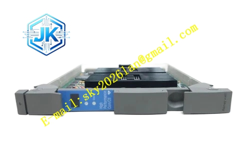
Description
Honeywell 51403158-100
Technical Specifications Bus Interface: LCN coaxial trunk and node tap port, BNC connectors Communication Rate: 5Mbps Power Supply: 5V DC Power Consumption: 5.2W Operating Temperature Range: 0℃ to 60℃ Storage Temperature Range: -40℃ to 85℃ Isolation Withstand Voltage: 1500V AC Relative Humidity: 5% to 95%, non-condensing
Functional Features It provides electrical isolation between the main LCN trunk and the connected node to limit fault propagation. It maintains stable 50Ω impedance matching for the LCN trunk bus during node tapping. It monitors the signal load of the tapping port and uploads overload alarm. It supports hot swap of the connected node without interrupting the communication of other nodes on the trunk. It suppresses signal reflection caused by node plugging and unplugging. It carries out signal filtering to reduce high-frequency noise from the node internal circuit.
Application Scenarios Independent node tapping access for GUS operator station and engineering station. Isolation access for HM history module, AM application module and CG control gateway. Fault isolation protection for key LCN nodes in large-scale TPS network. Replacement of aging tap units on LCN trunk lines of existing plants.
Performance Parameters Insertion Loss: ≤0.25dB Return Loss: ≥20dB Impedance Matching: 50Ω ±1Ω Signal Reflection Suppression Ratio: ≥90%
Material Composition PCB Substrate: Low-loss high-frequency FR-4 multi-layer board with strict impedance control Isolation transformer and LC impedance matching network High-frequency filter components Gold-plated BNC coaxial connectors Cold-rolled steel shielding shell Anti-static coated front panel
Structural Features Standard European pluggable card, suitable for LCN node rack dedicated tap slot. Front panel is equipped with run indicator light and tap port status indicator light. Three BNC connectors are arranged on the side for trunk input, trunk output and node tapping. The whole RF circuit area is wrapped by metal shielding structure to avoid external interference. All signal components are fixed with high-temperature resistant solder to adapt long-term cabinet operation.
Working Principle The module passes LCN trunk signals through the internal isolation and impedance matching network. It extracts a part of bus signal for the connected LCN node to receive and transmit. The isolation network cuts off the DC fault current from the node, so the node short-circuit fault cannot spread to the main trunk. It absorbs the signal reflection generated when the node is plugged or unplugged, and keeps the waveform integrity of the trunk bus. It detects the load current of the tapping port and triggers alarm when abnormal load appears.
Installation Requirements Insert the module vertically into the dedicated slot of LCN node rack and tighten fixing screws. Wire the LCN trunk cable in series through the trunk input and trunk output BNC ports. Connect the node communication cable to the tap port BNC connector. Check the trunk signal amplitude and return loss value on the LCN diagnostic screen after power on. All BNC connectors must be tightened completely to avoid loose contact.
Precautions Do not connect multiple nodes directly to one single tap port, which will cause bus impedance mismatch. Release static electricity before touching the module internal circuit. Mechanical deformation of the internal isolation transformer will lead to abnormal signal attenuation. The module cannot be used for UCN bus tapping, which is designed for LCN network only. Regular inspection of BNC connectors is required in high-humidity environments.







