



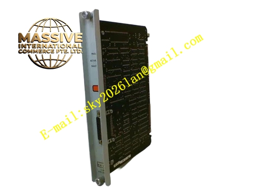
Description
Honeywell 620-0042
Technical Specifications
- Backplane Bus Interface: IPC620 proprietary I/O Link bus
- External Connector: DB25 D-Sub female connector on front panel
- Communication Physical Layer: RS232 / RS422 configurable
- Supported Baud Rate: 1200 bps to 19200 bps
- Parity Mode: None, Odd, Even configurable
- Stop Bit: 1 bit or 2 bits configurable
- Isolation Rating: 1000 VAC galvanic isolation between backplane side and external serial side
- Operating Supply: 5 VDC from rack backplane
- Operating Temperature: 0 °C to +60 °C
- Storage Temperature: -40 °C to +85 °C
- Relative Humidity: 5 % to 95 % non-condensing
- Hot Swap Support: Yes
- Mechanical Dimension: Standard IPC620 eurocard form factor
Functional Features Dual-direction protocol conversion between I/O Link bus and serial communication channel. Hardware CRC check for each transmitted and received communication frame. Real-time communication fault detection including frame error, parity error, timeout and break signal. Front panel three-color LED array indicates power status, transmit activity, receive activity and link fault. Independent frame buffer eliminates data overflow during high-speed burst data transmission. DIP switch bank on front panel selects physical interface mode, baud rate and parity setting. Transient surge suppression circuit protects serial port from static discharge and induced lightning spike. Event timestamp marking for communication abnormal records uploaded to PLC event register.
Application Scenarios IPC620 PLC connecting to industrial HMI operator panel Serial data transmission between IPC620 and upper SCADA host Remote programming and online monitoring access for IPC620 controller Legacy serial protocol equipment integration in chemical and power auxiliary control system Communication channel spare replacement for aging IPC620 control cabinet
Performance Parameters
- Maximum continuous data throughput: 1800 bytes per second
- Communication propagation delay: Less than 400 μs
- Frame error rejection rate: 100 % for frames failing CRC verification
- Fault reporting response time: Less than 250 ms
- ESD immunity: ±8 kV contact discharge, ±15 kV air discharge
Material Composition Main circuit substrate: Multilayer FR4 PCB with UL94 V0 flame retardant grade Communication transceiver: RS232/RS422 differential transceiver IC Protocol processing unit: Industrial FPGA logic chip Isolation component: High speed digital optocoupler array Protection component: TVS diode, ferrite noise suppression bead, ceramic decoupling capacitor External connector: Gold-plated DB25 D-Sub connector Front panel: Black flame retardant nylon plastic with locking extraction handle
Structural Features Standard plug-in eurocard structure matched with rack slot guide rail. DB25 connector and LED indicators are centrally arranged on front panel for convenient wiring and observation. Small removable plastic cover protects DIP switches from accidental touch. Internal isolation barrier separates rack backplane low voltage circuit and external serial signal circuit. Anti-keying mechanical notch prevents mis-insertion into analog or digital I/O card slots. Signal trace layout isolates high speed differential serial traces from digital logic traces to reduce crosstalk.
Working Principle The module receives process data packets from CPU through I/O Link backplane bus. FPGA chip unpacks the proprietary bus frame and repackages valid data into standard serial protocol format according to DIP switch configuration. Serial transceiver chip drives differential or single-ended signal and sends data to external host through DB25 port. When command data returns from external device, the module receives serial frame, executes parity and CRC verification, converts valid command into I/O Link bus frame, and transmits back to CPU. Onboard monitoring circuit continuously checks signal integrity and triggers fault flag once communication abnormality appears.
Installation Requirements Power down the rack before module installation or DIP switch configuration. Align the guide rail and push the module fully until the front panel locking latch clicks into fixed position. Use shielded serial cable matched with selected physical layer, and keep cable length within specification limit. Set consistent baud rate, parity and stop bit parameters on module and connected host device. Route serial cable separately from high voltage AC power cable in cable tray. Restore rack power and execute communication channel self-test in IPC configuration software after installation.
Usage Notes Do not switch DIP switch setting when the rack remains powered. Do not connect RS232 level signal to RS422 bus network without level converter. Dust contamination on DB25 connector pins causes intermittent communication dropout. Do not short circuit transmit and receive signal pins on DB25 port. Wear static protection wristband when taking out the module from anti-static packaging bag.







