



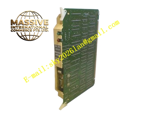
Description
Honeywell 620-0043
Technical Specifications
- Backplane Interface: IPC620 proprietary I/O Link backplane bus
- External Ports: Two DB25 serial ports, each configurable for RS232 or RS422
- Baud Rate Range: 1200 bps to 38400 bps per channel independent setting
- Parity Option: None, Odd, Even
- Stop Bit: 1 bit or 2 bits
- Channel Isolation: 1000 VAC isolation between each serial channel and backplane circuit
- Inter-channel Isolation: 500 VAC isolation between two serial ports
- Supply Voltage: 5 VDC supplied from rack backplane
- Operating Temperature: 0 °C to +60 °C
- Power Consumption: 4.9 W maximum
- Hot Swap Support: Yes
Functional Features Two fully independent serial communication channels with separate configuration parameters. Each channel supports Modbus RTU master mode and Modbus RTU slave mode. Per-channel frame CRC verification, parity error, framing error and timeout detection. Independent TX/RX LED indicator for each serial channel on front panel. Large capacity dual data buffer prevents packet loss under concurrent transmission of two channels. Configurable communication fault action, including freeze data or report fault to PLC register. Surge protection circuit for each serial port works independently. Communication diagnostic data of two channels can be uploaded separately to controller.
Application Scenarios IPC620 PLC connects HMI and remote RTU at the same time Dual Modbus RTU network integration for chemical batch control system Dual host redundant monitoring of IPC620 control rack Power plant auxiliary system two-way serial data forwarding Upgrade replacement of single-channel CIM module for IPC620 rack
Performance Parameters
- Single channel maximum throughput: 2400 bytes per second
- Dual channel simultaneous operation delay: Less than 500 μs
- Isolation withstand voltage: 1000 VAC for 60 seconds
- Common mode rejection ratio: 75 dB minimum
- Fault detection latency per channel: Less than 220 ms
Material Composition Multilayer FR4 UL94 V0 PCB, dual serial transceiver chips, FPGA protocol processing chip, multi-group optocoupler isolation components, precision current limiting resistors, TVS surge suppression diodes, tantalum and ceramic decoupling capacitors, two gold-plated DB25 connectors, UL94 V0 flame retardant plastic front panel with extraction handle.
Structural Features Standard eurocard plug-in size compatible with IPC620 rack slot. Two DB25 connectors are arranged side by side on front panel, matched with corresponding LED indicators. Separate isolation area is reserved for each serial channel on PCB layout. Independent DIP switch group for each channel is covered by plastic dust-proof cover. Anti-keying notch prevents installation into non-communication module slot. Heat dissipation copper area is laid under FPGA chip to stabilize temperature under full-load operation.
Working Principle I/O Link bus transmits read and write data commands from IPC620 CPU to onboard FPGA. FPGA distributes data to two serial channels according to configured routing rules. Each serial channel converts internal bus data into Modbus RTU or transparent serial frame and sends to external equipment. When receiving response frame from two external devices, each channel completes verification independently, and sends valid data back to CPU through I/O Link bus. Fault monitoring circuit tracks signal status of each channel separately, and generates independent fault flag for abnormal channel without affecting normal operation of another channel.
Installation Requirements Carry out power-off operation of rack before module installation and parameter configuration. Configure baud rate, parity, address and master-slave mode separately for channel 1 and channel 2. Use two independent shielded serial cables for two ports, do not share cable trunk. Set matching communication parameters on connected slave or host equipment. Check two-channel communication status separately in IPC software after power restoration. Tighten DB25 connector fixing screws to avoid loose contact caused by cabinet vibration.
Usage Notes Do not mix RS232 and RS422 bus wiring on the same channel. Do not connect two different Modbus networks to one serial channel. Short circuit of one serial port only triggers fault alarm of this channel and will not damage another channel. Do not modify internal routing logic by changing onboard resistor components. High baud rate long-distance transmission must use shielded twisted pair cable.







