



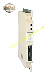
Description
Honeywell 620-0056
Technical Specifications
- Backplane Interface: IPC620 proprietary I/O Link backplane bus
- Redundancy Synchronization Port: Differential high speed dedicated synchronization bus
- Synchronization Data Rate: 1 Mbps
- Switchover Time: Less than 50 ms
- Isolation Rating: 1000 VAC galvanic isolation for synchronization port
- Supply Voltage: 5 VDC from rack backplane
- Operating Temperature: 0 °C to +60 °C
- Power Consumption: 4.8 W maximum
- Hot Swap Support: Yes
Functional Features High speed bidirectional synchronization of all runtime data between primary and standby CPU. Hardware-level bumpless control switchover without logic program interruption. Continuous comparison of data consistency between primary and standby controller. Redundancy fault diagnosis including synchronization cable break, data mismatch and CPU state abnormality. Front panel LED indicators show primary status, standby status, synchronization link and redundancy fault. Synchronization link frame carries CRC check to avoid error data synchronization. Redundancy switchover event is recorded with millisecond timestamp in PLC event log.
Application Scenarios Hot redundant IPC620 control rack for chemical critical continuous process Redundant control system of power plant boiler auxiliary equipment Unmanned remote pumping station redundant PLC control cabinet High availability water treatment process control system based on IPC620 Redundancy synchronization card spare replacement of IPC620 redundant rack
Performance Parameters
- Synchronization cycle: 1 ms
- Bumpless switchover delay: Less than 50 ms
- Isolation withstand voltage: 1000 VAC for 60 seconds
- Data mismatch detection response: Less than 300 ms
- Synchronization bus maximum cable length: 10 m dedicated differential cable
Material Composition Multilayer FR4 UL94 V0 PCB, high speed differential transceiver chip, FPGA synchronization control logic chip, optocoupler isolation devices, TVS surge suppression diodes, ferrite noise beads, gold-plated backplane edge connector, dedicated synchronization cable terminal block, flame retardant plastic front panel.
Structural Features Standard eurocard plug-in size matching IPC620 rack redundancy slot. Dedicated differential synchronization terminal block and redundancy status LED are arranged on front panel. Internal isolation barrier separates rack backplane circuit and synchronization bus circuit. Anti-keying notch prevents mis-insertion into ordinary communication or I/O slot. Differential synchronization traces adopt symmetrical length matching layout to ensure signal synchronization. Metal shielding cover reduces EMI interference to high speed synchronization signal.
Working Principle Two redundancy synchronization modules are installed in primary CPU rack and standby CPU rack respectively, connected by dedicated differential synchronization cable. The module reads real-time running data of local CPU through I/O Link backplane bus, transmits data to opposite module through high speed differential bus, and receives synchronization data from opposite CPU. FPGA logic compares data consistency of two sides continuously. When primary CPU fault is detected, synchronization module sends switchover instruction to standby CPU, standby CPU immediately takes over all control output without process interruption. Synchronization link abnormality will trigger redundancy fault alarm.
Installation Requirements Power down the whole redundant rack before module installation and synchronization cable wiring. Use the dedicated differential synchronization cable specified by Honeywell, do not replace with ordinary twisted pair. Keep synchronization cable length within 10 m limit, and avoid crossing high voltage power cable. Configure redundancy enable and primary/standby role in IPC configuration software. Simulate primary CPU fault test after commissioning to verify bumpless switchover function.
Usage Notes Two redundant racks must be equipped with one 620-0056 module respectively to form synchronization pair. Do not disconnect synchronization cable during normal running of redundant control system. Data inconsistency fault will trigger forced switchover and alarm. Do not modify onboard synchronization logic components. Static protection wristband must be worn during module replacement.







