



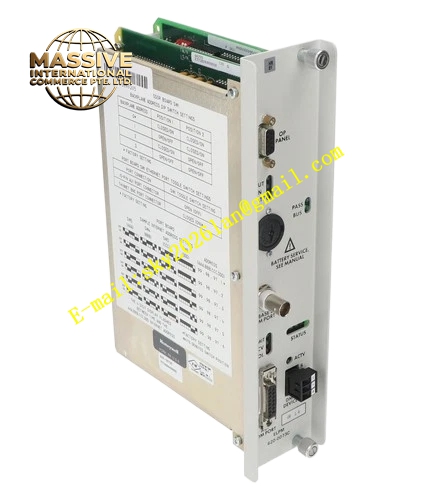
Description
Honeywell 620-0076
Technical Specifications
- Backplane Interface: IPC620 I/O Link backplane bus
- Field Termination: Screw terminal group supporting analog and discrete signals
- Loop Supply Output: 24 VDC regulated field power, 200 mA per group
- Signal Types Supported: 4-20 mA, 0-10 VDC, RTD, 24 VDC dry contact
- Group Isolation: 500 VAC reinforced isolation between backplane and field side
- Supply: 5 VDC from rack backplane
- Operating Temperature: 0 °C to +60 °C
- Power Consumption: 4.7 W maximum
- Hot Swap Support: Yes
Functional Features Regulated 24 VDC loop power supply for two-wire analog transmitters. Per-group short-circuit current limiting and automatic recovery protection. Field side surge and ESD protection for all signal terminals. Wiring break detection for analog current loops and RTD sensor circuits. Front panel LED indicates power status, bus communication and group fault condition. Signal path filtering to suppress high frequency field noise. All field diagnostic events upload to CPU fault register with time stamp.
Application Scenarios Centralized field wiring interface for mixed analog and discrete instrument signals Chemical plant control cabinet terminal distribution for pressure, flow and temperature transmitters Pump and valve feedback signal termination for auxiliary interlock systems Water treatment instrument wiring interface for remote instrument clusters Spare termination interface replacement for aging IPC620 cabinet wiring racks
Performance Parameters
- Loop supply regulation accuracy: ±1 %
- Short-circuit protection response: Less than 60 μs
- Isolation withstand voltage: 500 VAC for 60 seconds
- Common mode rejection ratio: 85 dB minimum
- Fault reporting latency: Less than 220 ms
Material Composition Multilayer FR4 PCB, voltage regulation IC, optocoupler isolation devices, current limiting power resistors, TVS surge suppression diodes, metal film sampling resistors, screw terminal blocks, gold-plated backplane edge connector, UL94 V0 flame retardant plastic front panel.
Structural Features Standard eurocard plug-in size compatible with IPC620 rack. Multiple screw terminal groups are arranged on front panel for convenient field wiring. Internal isolation barrier separates backplane low voltage logic and field signal area. Terminal marking silk screen clearly identifies signal type and polarity. Anti-keying notch prevents reversed insertion into pure communication module slots. Power distribution traces use wide copper area to reduce temperature rise under full load.
Working Principle The module receives I/O command and data frames from the IPC620 CPU through the backplane bus. Internal signal conditioning circuits route signals between backplane I/O modules and field terminal terminals. The onboard regulator generates stable 24 VDC supply for two-wire transmitters connected to terminal blocks. Current monitoring circuits detect overcurrent, open circuit and short circuit conditions on each signal group. Fault flags are generated and uploaded to the CPU when abnormal wiring state appears. Surge protection components absorb transient voltage spikes coming from field instrument cables.
Installation Requirements Tighten all field terminal screws to specified torque rating to avoid loose contact. Use shielded twisted pair cable for analog instrument wiring, single-point shield grounding inside cabinet. Separate analog signal terminals and discrete high-current output terminals in wiring layout. Disable unused loop power channels in configuration software to save power consumption. Check 24 VDC output voltage with multimeter before connecting field transmitters.
Usage Notes Do not connect AC voltage signals to field signal terminals. Overloaded 24 VDC loop supply triggers current limiting and shuts down power to the group. Shield double-point grounding introduces common mode noise and measurement deviation. Do not daisy-chain multiple terminal adapter modules on the same field instrument cable.







