



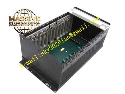
Description
Honeywell 620-10
Technical Specifications
- Backplane Bus: IPC620 I/O Link proprietary bus
- Processor Core: 32-bit industrial CPU
- Logic Memory: 512 KB RAM
- Program Storage: 2 MB non-volatile flash memory
- Supported I/O Modules: Full series IPC620 plug-in modules
- Operating Temperature: 0 °C to +60 °C
- Power Consumption: 7.2 W maximum
- Hot Swap Support: Yes, redundant CPU version available
Functional Features Execute ladder logic and functional block control programs. Synchronous scan of all I/O modules on rack backplane. Alarm threshold judgment, event timestamp recording and fault log storage. Program online download, upload and force function. Watchdog timer for program runaway protection. Front panel LED indicators for run, fault, communication and force status. Real-time clock for time stamping of all events and alarms.
Application Scenarios Core controller for chemical, oil & gas auxiliary control racks Power plant auxiliary equipment interlock and regulatory control Water treatment process main control unit Replacement of aging master CPU for existing IPC620 systems
Performance Parameters
- Minimum logic scan cycle: 1 ms
- Program retention time: 10 years minimum without power supply
- Watchdog timeout: 100 ms
- Clock accuracy: ±2 seconds per day
Material Composition Multilayer FR4 PCB, 32-bit industrial processor chip, flash memory chip, RAM chip, real-time clock chip with backup battery, optocoupler isolation devices, gold-plated backplane edge connector, UL94 V0 flame retardant plastic front panel.
Structural Features Standard eurocard plug-in form factor, occupies dedicated CPU slot of rack. Front panel LED group displays running state and fault information. Backup battery compartment sits on front panel for RTC power supply. Internal multi-layer ground plane separates analog, digital and power circuits. Anti-keying notch prevents installation into I/O module slots.
Working Principle After power on, CPU loads user control program from flash memory into RAM and starts cyclic scan. In each scan cycle, it sends request frames to each I/O module via I/O Link bus to collect field signal status. Control logic calculation is executed according to user program. Output commands are sent back to corresponding I/O modules. Alarm and event data are written to log storage and transmitted to communication module for host upload. Hardware watchdog continuously monitors program running state.
Installation Requirements Use dedicated CPU slot on IPC620 rack only. Replace backup battery regularly to maintain real-time clock accuracy. Download correct matching firmware and user program during commissioning. Set scan cycle and watchdog parameters in programming software. Verify all I/O modules can be identified by CPU after installation.
Usage Notes Program download will interrupt running control logic. Battery exhaustion causes loss of real-time clock, program and configuration will not be erased. Do not remove the module while rack is running for non-redundant single CPU system. Invalid user program will trigger watchdog fault and stop output.







