



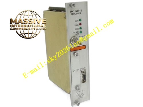
Description
Honeywell 620-1536
Technical Specifications
- Backplane Interface: IPC620 proprietary I/O Link backplane bus
- External Communication Port: 9-pin D-Sub serial port
- Processor Architecture: 32-bit industrial fixed-point processor
- Onboard RAM: 256 KB
- Non-Volatile Flash Memory: 1 MB
- Supply Power: 5 VDC sourced from rack backplane
- Operating Temperature: 0 °C to +60 °C
- Storage Temperature: -40 °C to +85 °C
- Relative Humidity: 5 % to 95 % non-condensing
- Hot Swap Support: Yes
- Maximum Power Consumption: 5.8 W
- Isolation Rating: 1000 VAC isolation between serial port and backplane logic circuit
Functional Features Local execution of independent control logic segments to reduce calculation burden on main CPU. Front-panel 9-pin D-Sub serial channel supports direct connection with Honeywell IPC configuration terminal. Hardware watchdog timer continuously monitors program execution flow and triggers fault state upon program runaway. Front panel multi-color LED indicators display power status, bus link health, program run state and internal fault alarm. All uploaded I/O and diagnostic data frames add CRC checksum for transmission integrity validation. Built-in non-volatile storage retains local logic configuration, setpoint parameters and event records through power loss cycles. It supports per-module fault timestamp marking for alarm and diagnostic events. It performs bus arbitration for local rack I/O modules when assigned as secondary controller.
Application Scenarios Distributed auxiliary control rack local processing for oil and gas metering skids Secondary control processor for boiler auxiliary equipment interlock loops Local logic processing unit for remote unmanned process monitoring stations Replacement spare processor for legacy IPC620 systems undergoing maintenance Sub-control unit for batch sequencing control in chemical formulation lines
Performance Parameters
- Minimum local logic scan cycle: 2 ms
- Watchdog timeout threshold: 120 ms
- Non-volatile data retention period: 10 years minimum
- Serial communication baud rate range: 1200 bps to 19200 bps
- Common mode rejection ratio: 84 dB minimum
- Fault reporting latency to main CPU: Less than 220 ms
Material Composition Main circuit substrate: Multilayer FR4 PCB with UL94 V0 flame retardant grade Processing core: 32-bit industrial microprocessor chip Memory devices: Flash memory chip and static RAM chip Signal isolation: High-speed optocoupler array for serial port isolation Protection components: TVS surge suppression diodes, ferrite beads, ceramic decoupling capacitors External connector: Gold-plated 9-pin D-Sub connector Backplane connector: Gold-plated edge finger connector Front panel: Black UL94 V0 flame retardant nylon plastic with integrated extraction latch
Structural Features Standard Eurocard plug-in dimension matching IPC620 rack guide slots. Front panel integrates 9-pin D-Sub port and status LED indicator bank in centralized layout. Internal isolation barrier separates external serial signal circuit and backplane logic circuit. Anti-keying mechanical notch prevents mis-insertion into analog I/O or communication module slots. Separate ground plane layout isolates digital logic traces from serial signal traces. Copper heat spreading area under processor chip stabilizes temperature under continuous full-load running. Dust-proof plastic cover protects rear DIP configuration switch bank.
Working Principle After rack power-on, the module loads stored local control logic from flash memory into RAM and initializes communication link with the primary IPC620 CPU over I/O Link bus. It collects status and measurement data from local I/O modules in each scan cycle, runs assigned control algorithms, and sends output commands back to corresponding I/O channels. It transmits process variables, alarm flags and diagnostic records to the main controller. The 9-pin serial port receives configuration commands from commissioning tools and outputs real-time tag data for on-site debugging. Hardware watchdog circuit triggers fault lockout if the program execution cycle exceeds preset limit.







