



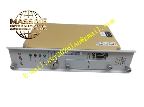
Description
Honeywell 620-1537
Technical Specifications
- Backplane Interface: IPC620 proprietary I/O Link backplane bus
- Redundancy Sync Interface: Dedicated internal high-speed synchronization bus
- Processor Architecture: 32-bit industrial fixed-point processor
- Onboard RAM: 512 KB
- Non-Volatile Flash Memory: 2 MB
- Supply Power: 5 VDC from rack backplane
- Operating Temperature: 0 °C to +60 °C
- Storage Temperature: -40 °C to +85 °C
- Relative Humidity: 5 % to 95 % non-condensing
- Hot Swap Support: Yes
- Maximum Power Consumption: 6.7 W
- Isolation Rating: 1000 VAC isolation for external serial debug port
- Switchover Response Time: Less than 5 ms
Functional Features Continuous real-time synchronization of I/O image, control setpoints and logic state between master and standby processor. Automatic bumpless switchover to backup processor upon master CPU fault, communication loss or watchdog trip. Independent hardware fault detection circuit monitors master processor operation and synchronization channel integrity. Front panel LED indicators show master/standby role status, power supply, bus communication, synchronization link and fault alarm. Dedicated synchronization channel carries state mirroring data with hardware error checking. It supports online diagnostic viewing of redundancy state and synchronization offset. All event logs record switchover timestamp and root fault cause. It accepts the same programming tool and logic program files used for 620-1536 processor modules. CRC checksum applies to all synchronization data packets to avoid state corruption.
Application Scenarios High-availability safety-related auxiliary control racks in power generation plants Critical pressure and flow regulation control for oil and gas production skids Continuous chemical process closed-loop control requiring zero interruption Unattended remote pipeline monitoring and interlock control systems Legacy IPC620 redundant control rack spare replacement
Performance Parameters
- Minimum logic scan cycle: 2 ms
- Watchdog timeout threshold: 120 ms
- State synchronization refresh interval: 0.5 ms
- Non-volatile data retention period: 10 years minimum
- Common mode rejection ratio: 84 dB minimum
- Switchover deviation of control output: Less than 0.1 % of full scale
- Fault reporting latency: Less than 220 ms
Material Composition Main circuit substrate: Multilayer FR4 PCB with UL94 V0 flame retardant grade Processing core: 32-bit industrial microprocessor chip Memory devices: Flash memory chip and static RAM chip with expanded capacity Redundancy control: Dedicated FPGA chip for synchronization and state arbitration Signal isolation: High-speed optocoupler array for debug serial port isolation Protection components: TVS surge suppression diodes, ferrite noise suppression beads, precision sampling resistors Backplane connector: Gold-plated edge finger connector Front panel: Black UL94 V0 flame retardant nylon plastic with extraction latch and LED array
Structural Features Standard Eurocard plug-in size fully compatible with IPC620 rack dedicated processor slot. Front panel LED group separately identifies master mode, standby mode and sync channel fault. Internal dedicated differential trace pair for redundancy synchronization communication. Internal isolation barrier separates debug serial port circuit and backplane logic domain. Anti-keying mechanical notch prevents mis-insertion into non-processor I/O slots. Enhanced copper thermal layout accommodates higher power dissipation during synchronization operation. Dust cover protects configuration switches for redundancy mode setup.
Working Principle When the rack starts, one processor enters master active state and the other enters standby backup state. The master processor runs control logic, reads I/O modules and issues output commands. The standby processor mirrors all I/O table values, setpoints and intermediate calculation states continuously through the dedicated synchronization bus. The standby processor runs the same control program in lockstep without driving output channels. The fault monitor circuit checks master heartbeat and synchronization data validity constantly. Once master failure is confirmed, the standby processor immediately switches to master role, takes over all I/O bus control and continues control execution without output bump. Fault and switchover events write to onboard event storage and upload to system alarm registers.
Installation Requirements Install 620-1537 paired with matching master processor in designated redundant processor slots on IPC620 rack. Power down rack before setting redundancy configuration switches. Download identical firmware and user logic program to both processors. Verify synchronization link status LED shows normal lock after power-up. Perform forced master fault test during commissioning to validate bumpless switchover action. Separate debug serial wiring from high voltage power cables. Configure system alarm logic for redundancy switchover notification in host SCADA.







