



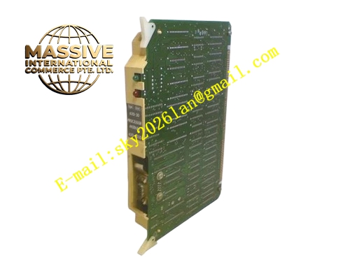
Description
Honeywell 620-2032
Technical Specifications
- Channel count: 8 independent relay output channels
- Supported load voltage: 24 V DC / 220 V AC
- Maximum per-channel load current: 2 A
- RC snubber network parameter: 0.1 μF capacitor in series with 100 Ω resistor
- Freewheeling diode rating: 100 V withstand voltage, 1 A rated current
- Terminal torque rating: 0.5 N·m to 0.7 N·m
- Operating temperature: 0 °C to +60 °C
- Relative humidity: 5% to 95% non-condensing
Functional Features Per-channel RC snubber network suppresses voltage spikes generated when inductive loads disconnect. Per-channel 24 V DC freewheeling diode diverts coil reverse EMF for inductive loads. Silk-screen labels mark normally open, normally closed and common terminal positions, reduces wiring errors. Per-channel resettable fuse, short circuit on one channel does not disrupt remaining output circuits. Physical separation between low-voltage and high-voltage terminal zones to reduce cross-interference.
Application Scenarios Solenoid valve and shutoff valve coil drive circuit termination Audible alarm horn and status beacon light control Pump and fan local relay coil drive circuits Auxiliary cabinet discrete load wiring with contact feedback diagnosis Spare relay output channel replacement for aging IPC620 control racks
Performance Parameters
- RC snubber network withstand voltage: 600 V peak
- Freewheeling diode response time: ≤1 μs
- Surge tolerance: ±6 kV contact electrostatic discharge
- Terminal contact resistance: ≤15 mΩ
- Insulation resistance: ≥1000 MΩ
Material Composition FR4 flame retardant PCB substrate High voltage ceramic capacitors, metal film current limiting resistors Power freewheeling diodes, resettable fuses Tin-plated copper alloy screw terminals Nylon terminal guard covers Powder-coated cold rolled steel mounting bracket
Structural Features Long rectangular PCB form factor, fits IPC620 lower terminal compartment. Screw terminals split between control signal zone and high-voltage load zone. Physical partition separates low-voltage drive logic area and high-voltage contact area. Mounting holes positioned for direct screw fixation to cabinet mounting bracket.
Working Principle Switch control commands from the upstream output module travel via flat cable to this terminal board, then route to external field loads. When driving inductive loads such as solenoid valves and relays, the reverse EMF generated at coil disconnection is absorbed by the RC snubber network and freewheeling diode, preventing voltage spikes from damaging upstream relay contacts. Per-channel resettable fuse detects load short circuit, cuts power to the affected channel to protect the upstream module.
Installation Requirements Verify external load voltage and current stay within the relay contact rating. Install freewheeling diode or surge suppressor at inductive load terminals. Route relay load wiring separately from low-voltage instrument signal cables. Wire RC snubber and freewheeling diode polarity strictly per silk-screen marking. Test each channel actuation sequence after installation before bringing the process online.
Usage Notes Inductive loads accelerate relay contact erosion even within rated current limits. Contact weld fault cannot be cleared by software reset, requires module replacement. Do not connect high-voltage AC signals to low-voltage backplane or logic terminals. Audible clicking sound during load switching is normal mechanical relay operation.







