



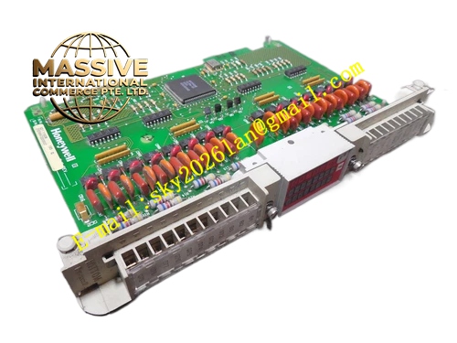
Description
Honeywell 620-6555R
Technical Specifications
- Input power: Two independent 24 V DC redundant inputs
- Output power: Single regulated 24 V DC continuous output
- Switchover time: ≤1 ms, no perceptible disturbance to downstream loads
- Switchover voltage drop: ≤0.1 V
- Rated output current: 10 A
- Input isolation: 500 V DC electrical isolation between the two input channels
- Operating temperature: 0 °C to +60 °C
- Status indication: 3 LEDs for input A status, input B status, normal output
Functional Features Diode-based redundancy topology, no reverse current cross-flow between the two power supplies. Seamless switchover, no voltage dip on the downstream load when one supply fails. On-board LEDs indicate the health status of both redundant inputs and active output. Independent overcurrent and overtemperature protection, automatically limits output current on short circuit. On-board EMI surge suppression, diverts lightning and switching transients on power lines. Hot swap compatible, individual power supply units can be replaced online without interrupting load power.
Application Scenarios Redundant power switchover for IPC620 high-availability control systems Uninterrupted power supply for critical interlock control loops Fault-free power continuity for petrochemical and power plant control loops Power reliability upgrade for legacy single-supply control cabinets
Performance Parameters
- Diode forward voltage drop: 0.3 V
- Load current sharing imbalance: ≤5%
- Overtemperature protection threshold: 85 °C, automatic output shutdown
- Switch life: No mechanical components, unlimited theoretical service cycles
- Standby quiescent current: ≤5 mA
Material Composition High thermal conductivity FR4 PCB substrate High-current Schottky power diodes TVS surge suppression components Green status indicator LEDs Tinned copper heat dissipation bus bar Tin-plated copper alloy high-current screw terminals Anodized aluminum heat sink mounting enclosure
Structural Features Long rectangular metal heat sink enclosure, DIN rail mountable inside the cabinet. Front face arranges two input terminals and one output high-current terminal. Integrated cooling fins on the enclosure, assist heat dissipation for power diodes. LED status array arranged on the front panel. Silk-screen labeling defines input and output polarity for each terminal.
Working Principle Two independent 24 V DC supplies connect to the module inputs, each in series with a high-current Schottky diode. Diode outputs tie together to feed the downstream load. Under normal operation, the supply with slightly higher voltage conducts through its series diode to power the load, while the other diode remains reverse-biased. If the active supply fails, the other supply immediately conducts through its series diode, completing seamless switchover to maintain load power without interruption. Over-temperature protection circuit monitors internal component temperature, cuts output power if temperature exceeds safe limits.
Installation Requirements Connect the two redundant power supplies to independent circuit branches, never tie both inputs to the same supply. Use minimum 2.5 mm² cable for output wiring, terminate high-current connections securely. Connect the metal enclosure to the cabinet protective ground. Mount the module in a ventilated position, do not block the heat sink fins with cabling. Verify LED status after power-up, confirm both redundant supplies are properly connected.
Usage Notes Never exceed 10 A rated output current, overload causes diode overheating and failure. Single redundant supply replacement does not require load power shutdown, supports online hot swap. Diode forward voltage drop increases slightly with load current, this is normal conduction behavior. Never apply reverse voltage to the output terminals, this reverse-biases and destroys internal diodes.







