



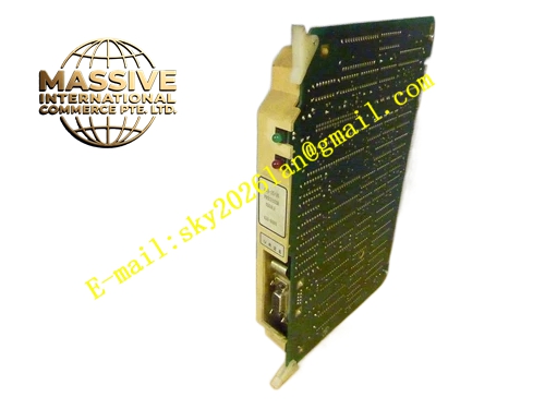
Description
Honeywell 620-8995
Technical Specifications
- Supply power: 24 V DC, drawn from cabinet power bus
- Status indication: 4 LEDs for power normal, communication normal, system fault, rack alarm
- Operation keys: 3 membrane pushbuttons for test acknowledge, alarm silence, channel test
- Communication interface: Flat cable connects to rack backplane status port
- Operating temperature: 0 °C to +60 °C
- Panel protection rating: IP20, for internal cabinet installation
- Pushbutton mechanical life: 1,000,000 operations
Functional Features Centrally displays global rack operating status, eliminating the need to inspect individual board LEDs across the rack. Local test buttons support alarm bypass and manual channel test triggering for routine maintenance. Integrated buzzer on the panel, emits audible alarm when system faults occur. Pushbutton debounce logic, prevents mechanical key bounce from triggering false operations. Flat cable connection for fast, reliable backplane mating. Silk-screen labeling clearly defines the function of each button and LED.
Application Scenarios Local status inspection for IPC620 cabinet racks On-site channel testing and alarm acknowledgment by maintenance staff Local audible and visual alarm for unattended cabinet sites On-site operation display retrofit for legacy control cabinets
Performance Parameters
- Pushbutton response time: ≤10 ms
- Buzzer sound pressure level: 85 dB(A) at 10 cm distance
- LED brightness: 100 mcd, clearly visible inside the cabinet
- Communication response latency: ≤50 ms
- Insulation resistance: ≥100 MΩ
Material Composition ABS flame retardant plastic front panel Membrane micro-switch pushbuttons Through-hole LED indicators Piezo buzzer Flexible flat connection cable FR4 PCB control board
Structural Features Rectangular flush-mount panel, designed to clip into the cabinet door cutout. LEDs and pushbuttons arranged on the front face, aligned with silk-screen function labels. Rear flexible flat cable mates to the rack backplane status interface. Sealing rubber strip around the panel, blocks cabinet dust ingress. Wear-resistant silk-screen printing on the front panel, no label peeling over long operation.
Working Principle The panel continuously reads rack status data from the backplane via the flat cable, illuminating corresponding LEDs to display power, communication and fault status. When a fault occurs, the on-board buzzer activates to send an audible alarm. When maintenance staff press pushbuttons, operation signals are sent via the flat cable to the CPU to execute alarm acknowledgment and channel test functions. Pushbutton debounce logic filters mechanical contact bounce, ensuring a single physical press triggers exactly one operation command.
Installation Requirements Clip the panel flush into the cabinet door cutout, secure without wobble. Connect the flat cable to the backplane interface, confirm the connector seats fully. Wire 24 V DC power to the correct polarity, reversed connection prevents operation. Mount the panel at 1.5 m above floor level, convenient for inspection and operation.
Usage Notes Do not break the panel sealing strip during installation, this allows dust ingress. Apply moderate force when pressing keys, never poke keys with sharp objects. Buzzer failure does not affect core control system operation, it only removes local audible prompt. Do not sharply bend the flat cable at radius less than 2 cm, this breaks internal wire conductors.







