



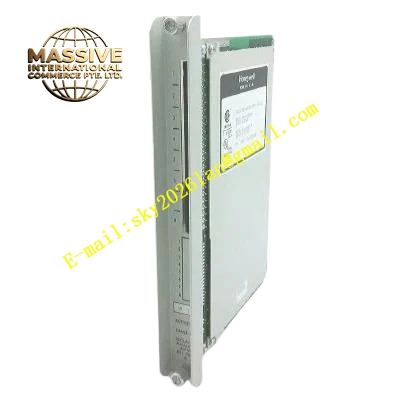
Description
Honeywell 621-0022-AR
Technical Specifications
- Slot count: 5 general-purpose I/O module slots
- Bus type: 621 expansion I/O bus
- Expansion interface: High-speed flat expansion cable port
- Backplane power: 5 V DC bus supply, 24 V DC field power distribution bus
- Operating temperature: -10 °C to +65 °C
- Corrosion rating: Conformal coated, rated for salt mist and high-humidity environments
Functional Features 5 universal slots support flexible configuration of different I/O module types for point count expansion. On-board bus termination resistors, eliminates signal reflection from long-distance expansion communication. Gold-plated finger contacts, reliable long-term insertion connection. 24 V DC power bus runs through all slots, provides field power for I/O terminals. Connects to the main rack via dedicated expansion cable, plug-and-play operation. Conformal coating provides resistance to offshore, coastal corrosive environments.
Application Scenarios 621 control system I/O point count expansion Remote I/O rack backplane in corrosive environment plants Spare part replacement for legacy system I/O rack capacity upgrades Skid-mounted equipment control system expansion rack components
Performance Parameters
- Maximum expansion cable communication distance: 10 m shielded twisted pair
- Bus signal reflection attenuation: ≥-25 dB
- 5 V DC bus current rating: 15 A continuous
- Slot insertion life: 500 mating cycles
- Insulation resistance: ≥2000 MΩ
Material Composition Thick FR4 PCB substrate Acrylic conformal coating layer Gold-plated edge fingers Precision termination resistor network Expansion cable connector Powder-coated steel mounting brackets
Structural Features Long rectangular PCB, with 5 evenly spaced I/O module slot positions. Dedicated expansion cable interface on the side edge, connects to the main rack backplane. Silk-screen numbering for each I/O slot position. Grounding posts collect module shielding grounds. Mounting holes aligned to cabinet upright fixing positions.
Working Principle The main rack connects to this backplane via expansion cable. The CPU sends I/O communication data over the expansion bus to this backplane, assigning communication addresses to every installed I/O module. The power supply unit delivers 5 V DC power via the backplane bus to all I/O modules, while the 24 V DC field power bus supplies terminal loop power. Termination resistors absorb signal reflection at the end of the long expansion bus, ensuring error-free long-distance communication.
Installation Requirements Mount the backplane flat, tighten mounting screws diagonally. Seat the expansion cable connector fully, lock the clips to prevent vibration loosening. Align I/O modules with slot guides when inserting, press until gold fingers are fully seated. Connect grounding posts reliably to the cabinet protective ground.
Usage Notes Expansion cable length must not exceed 10 m, longer runs cause signal distortion and communication failure. Clean oxidized gold fingers with a rubber eraser — never sand the gold plating. Coating damage reduces corrosion protection performance, evaluate unit replacement based on environmental conditions.







