



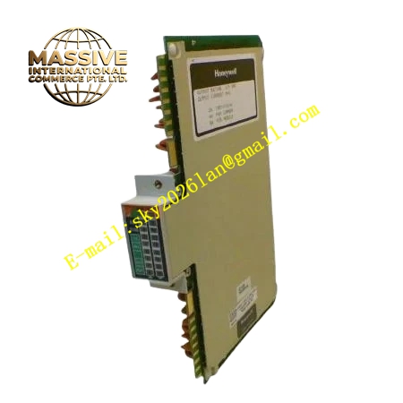
Description
Honeywell 621-2150
Technical Specifications
- Channel count: 16 isolated digital input channels
- Input signal type: 24 V DC sinking dry contact or active signal
- Channel isolation: 1500 VAC per channel optical isolation
- Debounce time: Software configurable 1 ms to 20 ms per channel
- Backplane interface: 621 parallel I/O bus
- Operating temperature: 0 °C to +60 °C
- Power consumption: 4.4 W maximum
- Hot swap support: Yes
Functional Features Independent optical isolation for every 16 input channels. Software-adjustable debounce filter eliminates mechanical contact bounce. Per-channel open-wire diagnostic detection for field wiring faults. Front panel LED indicator per channel, displays real-time input state. All input status data is packaged with CRC checksum before transmission to CPU. Group fault flag reports module communication or power abnormality.
Application Scenarios Limit switch and safety interlock signal collection for process valves Pump, fan and motor auxiliary contact feedback monitoring Pressure, level and flow switch status acquisition for alarm interlock loops Safety cabinet discrete signal input expansion for 621 control racks Spare digital input channel replacement for existing control systems
Performance Parameters
- Input response delay: Matches configured debounce setting
- Isolation withstand voltage: 1500 VAC for 60 seconds
- Input turn-on threshold: 18 V DC minimum, turn-off threshold: 5 V DC maximum
- Fault detection response: ≤180 ms for open wire events
Material Composition FR4 PCB substrate High-speed optocoupler isolators RC debounce filter components Current limiting resistors TVS surge suppression diodes Gold-plated backplane edge finger connector UL94 V0 flame retardant plastic front panel
Structural Features Standard Eurocard plug-in dimensions compatible with the 621 rack. Two rows of channel LED indicators arranged on the front panel for easy status checking. Internal isolation barrier separates field 24 V DC signal area and backplane logic area. Anti-keying notch prevents reversed insertion into analog output module slots. Independent circuit layout for each channel, eliminates cross-channel interference.
Working Principle Field 24 V DC signal or dry contact closure provides current path through the channel current limiting resistor and optocoupler LED. The optocoupler converts field voltage signal into isolated logic level for the onboard sampling circuit. Sampled channel status is grouped and packed into I/O Link bus frames and uploaded to the 621 CPU. Debounce timer logic rejects fast transient state changes caused by mechanical contact bounce. Wire break detection circuit judges open circuit condition by monitoring input leakage current level.
Installation Requirements Use twisted pair cable for field switch wiring. Separate discrete input wiring from high-current relay output wiring. Set debounce time value in configuration software according to mechanical switch characteristics. Verify channel state changes synchronously with field switch action after commissioning.
Usage Notes Never connect AC high voltage directly to digital input terminals. Long field wiring runs increase induced noise and false triggering risk. Debounce time set too short causes unstable status reading for old mechanical switches. Do not modify onboard current limiting resistors for input channels.







