



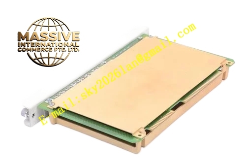
Description
Honeywell 621-9939C
Technical Specifications
- Channel count: 6 thermocouple input channels
- Supported thermocouple types: J, K, T, E, S, R
- Cold junction compensation accuracy: ±0.3 °C
- ADC resolution: 16-bit
- Measurement range: -200 °C to +1600 °C
- Coating dielectric strength: 10 kV/mm
- Operating temperature: -10 °C to +65 °C
- Backplane interface: 621 parallel I/O bus
- Hot swap support: Yes
Functional Features On-board PT100 cold junction compensation, eliminates measurement deviation caused by terminal block temperature variation. Millivolt signal instrumentation amplifier, compatible with long thermocouple extension cable runs. Independent per-channel open-circuit detection, triggers channel fault alarm for disconnected thermocouples. Software-configurable thermocouple type per channel. Digital low-pass filter smooths high-temperature readings, suppresses electromagnetic interference-induced signal jump. Conformal coating protects circuits against high humidity and corrosive gas in harsh plant environments. All acquired temperature values carry CRC checksum for upload integrity.
Application Scenarios Furnace and boiler chamber high-temperature measurement Heat treatment process temperature monitoring Flue and exhaust gas temperature measurement Reactor wall high-temperature monitoring in offshore and coastal chemical plants Spare part replacement for high-temperature measurement channels in corrosive environments
Performance Parameters
- Measurement accuracy: ±0.2 °C
- Sample rate: 20 Hz per channel
- Common mode rejection ratio: ≥90 dB
- Open circuit detection response: ≤250 ms
- Zero-point temperature drift: ±25 ppm/°C
Material Composition Low-noise FR4 PCB substrate Transparent acrylic conformal coating layer High-precision instrumentation operational amplifier 16-bit ADC chip PT100 cold junction compensation element Optocoupler isolation devices TVS surge protection diodes Gold-plated backplane edge finger connector
Structural Features Standard Eurocard plug-in dimensions for 621 rack I/O slots. Front screw terminals silk-screened with thermocouple polarity markings. Rear gold fingers mate directly to the backplane bus. Shielded enclosure around low-noise analog circuit area, isolates digital circuit interference. Cold junction compensation element positioned adjacent to terminal block, maintains compensation accuracy. PCB traces and component leads fully covered by transparent conformal coating.
Working Principle Thermocouple millivolt signal generated by temperature difference travels via extension cable to the module terminals. The on-board PT100 measures cold junction temperature at the terminal block, the instrumentation amplifier scales the millivolt signal to ADC input range. The ADC converts analog voltage to digital value, internal logic references the thermocouple lookup table to calculate actual process temperature. Loop impedance monitoring identifies sensor open circuit faults and generates fault flags. Processed temperature data is packaged into bus frames and uploaded to the PLC CPU.
Installation Requirements Use thermocouple extension cable matched to the sensor type, never substitute standard copper wire. Route extension cables separately from power cable trays to avoid induced interference. Configure thermocouple type per channel in software. Prevent direct air conditioning blow on the terminal block, maintain stable cold junction temperature. Avoid scratching the PCB conformal coating during installation.
Usage Notes Reversed extension cable polarity causes reversed temperature reading deviation. Never connect external power signals to thermocouple terminals, high voltage will destroy the amplification circuit. Recalibrate cold junction compensation annually to maintain high-temperature measurement accuracy. Damaged conformal coating reduces corrosion protection performance, replace the module as needed.







