



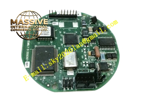
Description
Honeywell 82407021-001
Technical Specifications
- Compatible slot: HPM main processor board dedicated daughter slot
- I/O Link channel count: 8 independent bus channels
- Maximum connected I/O modules per channel: 16
- Communication rate: 1 Mbps
- Onboard memory: 128 KB data buffer
- Supply power: 5 V DC supplied by the main processor board
- Operating temperature: 0 °C to +60 °C
Functional Features Dedicated FPGA logic handles I/O Link bus communication, does not consume main processor compute resources. 8 channels operate in parallel, drastically reducing total I/O scan cycle time. CRC communication verification for all data frames, ultra-low data transmission error rate. Per-channel bus fault diagnosis, automatically identifies channel disconnection and module communication failures. Per-channel LED indicator, provides visible bus health status for maintenance. On-board bus termination resistors, eliminates long-distance signal reflection.
Application Scenarios Field I/O expansion for TDC3000 HPM controllers Spare part replacement for bus communication faults in legacy HPM systems I/O interface assembly for new chemical plant HPM installations Expansion retrofits for existing process control I/O capacity
Performance Parameters
- Single-channel scan cycle: 5 ms
- Communication latency: ≤1 ms
- Fault detection response: ≤100 ms
- Data buffer hit rate: ≥99%
- Maximum bus transmission distance: 30 meters shielded twisted pair
Material Composition FR4 high-speed PCB substrate FPGA communication logic chip High-speed SRAM buffer chip Gold-plated board-to-board connector Optocoupler isolation devices TVS surge protection diodes
Structural Features Small rectangular PCB daughter board. Rear gold fingers plug directly into the HPM main processor board slot. Front flat cable connectors interface to field I/O subracks. Channel silk-screen labels printed next to each connector. Impedance-controlled trace layout matches I/O bus 120 Ω characteristic.
Working Principle After power-up, the board FPGA initializes I/O Link communication logic, polling connected field I/O modules across 8 bus channels in fixed order. Output commands from the main processor are sent to corresponding I/O modules via the bus; collected field input data returns to the board buffer. The main processor reads buffered data as needed for logic computation. Bus monitoring circuits continuously check communication signal integrity, generating channel fault flags to the main CPU when communication is lost. Termination resistors absorb signal reflection at the bus end, ensuring reliable long-distance communication.
Installation Requirements Insert the daughter board into the dedicated slot only when power is off, press evenly until gold fingers are fully seated. Connect I/O bus flat cables to matching channel positions, lock the connector clips to prevent loosening. Check LED status after power-up, confirm all connected I/O modules are detected by the main processor. Wear an anti-static wrist strap when handling the board to avoid ESD damage to the FPGA.
Usage Notes Hot-swapping the daughter board causes all connected I/O channels to drop offline, triggering process alarms. Oxidized connector contacts cause channel dropouts; clean gold contacts regularly. Daughter board firmware version must match the HPM main processor firmware; mismatched versions prevent board recognition. Never short on-board termination resistors, this causes bus signal reflection and communication failure.







