



Description
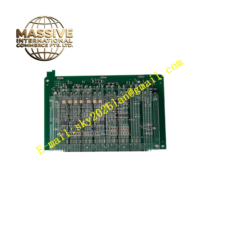
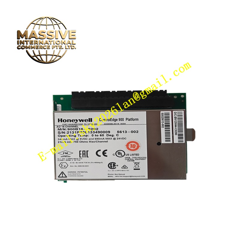
Honeywell 900B16-0202
Technical Specifications Multiple isolated digital input channels; supports dry contact and 24V DC discrete signals; channel isolation protection; backplane bus power supply; built-in input filtering circuit; diagnostic function for open circuit and abnormal signal state.
Functional Features Captures field switch state and transmits status data to the controller. Isolation circuits suppress ground loop interference and surge pulse from field equipment. Independent filtering on each channel eliminates signal jitter caused by mechanical contact bounce. Fault diagnosis function uploads abnormal channel information to HMI alarm window. Single channel failure does not affect signal collection of other channels.
Application Scenarios Chemical plants, water treatment stations, power auxiliary equipment and general industrial automation projects that adopt Honeywell 900 PLC control system.
Performance Parameters Fast state response; stable signal identification under industrial electromagnetic interference; long-term continuous operation stability; clear state distinction between on and off signals.
Material Composition Circuit board substrate is FR-4 flame-retardant multilayer PCB; signal acquisition chip and optocoupler isolation components are industrial grade; backplane connector contacts adopt gold plating; terminal base shell is flame-retardant PC plastic; terminal conductive parts are nickel plated.
Structural Characteristics Rack plug-in module structure; front panel is equipped with LED indicator lights for running state, fault state and each channel signal state; gold fingers at the rear are matched with the backplane of Honeywell 900 rack; anti-misinsertion positioning pins prevent reverse installation; the module is fixed on the rack by screws.
Working Principle Field discrete switch signals enter the terminal base, pass through isolation and filtering circuits, and are converted into standard logic level signals. The module reads the level state, packages the data and sends it to the controller through the backplane bus. The module continuously monitors the signal loop and sends fault alarm information when abnormal state is detected.
Installation Requirements Cut off the power supply of the control cabinet before installation. Push the module into the designated slot of the 900 rack and tighten the fixing screws. Use shielded cables for field signal wiring, and the shielding layer adopts single-point grounding. Set input filter parameters through Honeywell configuration software after power on.
Precautions for Use Anti-static protection must be carried out during handling. Hot plug and unplug of the module is prohibited. Signal cables should be laid separately from high-voltage power cables. When channel abnormality occurs, check field contacts and wiring first. There are no parts that can be maintained by users inside the module.







