



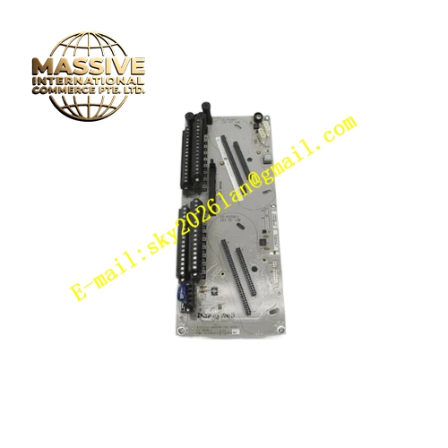
Description
Honeywell CC-SDOR01
Technical Specifications Multi-channel redundant digital output termination; 24VDC field load signal; per-channel built-in transient surge suppression; backplane 24VDC power supply; supports dual redundant IOM connection; operating temperature 0℃ to 60℃; storage temperature -40℃ to 85℃; relative humidity 5% to 95% non-condensing; rack slot mounting; UL, CE and Class I Division 2 hazardous area certification.
Functional Features It concentrates critical interlock actuator wiring onto labeled screw terminals. It absorbs reverse electromotive force surge from field inductive solenoid and relay coils. It receives control signals from two redundant digital output IOM modules simultaneously through dual backplane connectors. It maintains continuous field load connection during primary and standby IOM switching. It cooperates with IOM module to detect channel short-circuit and overload fault.
Application Scenarios ESD solenoid valve signal termination for refinery emergency shutdown cabinets; critical interlock relay wiring base for chemical plant reactor safety system; shutdown actuator output termination for offshore platform control cabinets.
Performance Parameters Redundant IOM switching completes without field load state jump; surge protection circuit keeps valid during hot-swap operation; fault alarm information transmits to Experion station within controller scan cycle.
Material Composition Housing uses flame-retardant polycarbonate; internal circuit substrate is FR4 flame-retardant PCB with conformal coating; terminal conductive shrapnel and screws are tin-plated copper alloy; surge protection components are wide-temperature industrial semiconductors; backplane contact pins are gold-plated; metal locking bracket uses anti-rust coated cold rolled steel.
Structural Characteristics Redundant rack-mount termination base; front panel printed with channel number and load type labels; rear dual backplane connector interfaces for primary and standby digital output IOM cards; mechanical fool-proof keying notch to prevent non-redundant IOM mismatching; side elastic latches for fastening to rack rail.
Working Principle Primary and standby redundant IOM modules send identical digital control signals to CC-SDOR01 via two independent backplane connectors. The IOTA routes the signal to field solenoid or relay loads after surge suppression. When the primary IOM module fails, the standby module takes over control output, and the IOTA maintains uninterrupted circuit connection for field loads. It does not make logic selection and only provides signal path and protection.
Installation Requirements Mount the IOTA base on standard Experion Series C rack rails. Confirm mechanical key matches redundant digital output IOM card. Use shielded twisted-pair cable for safety interlock actuator wiring. Separate interlock output cables and ordinary control cables. Tighten all field terminal screws to specified torque. Ensure cabinet reliable protective grounding.
Usage Notes Only pair this IOTA with redundant digital output IOM module set. Test redundant bumpless switchover function after commissioning. Wear anti-static wrist strap during IOM hot-swap replacement. Do not remove the IOTA base while interlock loops are energized.







