



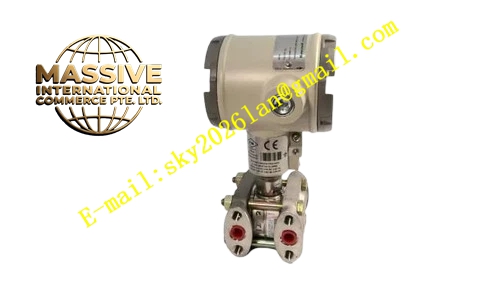
Description
Honeywell CN7505A2001C
Technical Specifications
- Torque rating: 5 Nm continuous rotary output
- Control signal: 0–10 V DC analog proportional input
- Supply voltage: 24 V AC/DC
- Rotation angle: 95° full stroke
- Running time: 30 seconds for full 95° travel
- Protection rating: IP54
- Operating temperature: -20 °C to +60 °C
Functional Features Spring return fail-safe function, drives the damper to fully open or fully closed position on power loss. Manual override crank, allows damper positioning during commissioning without applying power. Position feedback potentiometer, returns actual damper angle to the control system. Integral auxiliary switch, outputs end-of-travel contact signals. Direct mechanical coupling to damper shafts, no external gearbox required. LED position indicator, displays actuator run status from a distance.
Application Scenarios HVAC air handling unit damper control Process furnace combustion air flow adjustment Ventilation smoke damper fail-safe operation Spare part replacement for faulty rotary damper actuators in existing HVAC systems
Performance Parameters
- Position accuracy: ±2% full stroke
- Gear train noise level: ≤45 dB at 1 meter distance
- Spring return time: ≤10 seconds full stroke on power loss
- Auxiliary switch rating: 5 A / 24 V AC
- Shaft coupling size: Accepts 10 mm square or round damper shafts
Material Composition Glass-filled nylon gear housing Stainless steel drive shaft NBR elastomer return spring Brass terminal screws Die-cast aluminum end plates ABS plastic end cap
Structural Features Rectangular compact plastic housing. Bottom output shaft couples directly to the damper axle. Side manual override crank lever. Rear cable gland for power and control wiring. Front position scale marks travel angle.
Working Principle The control system sends a 0–10 V DC signal corresponding to desired damper position. The internal control circuit compares the signal to the feedback potentiometer position, driving the synchronous motor until the actuator shaft reaches the target angle. On power loss, the pre-tensioned return spring releases, rotating the shaft to the pre-set fail-safe position. The auxiliary switch triggers at full open and full closed positions, sending end-of-travel signals back to the controller.
Installation Requirements Mount the actuator directly on the damper shaft, secure the coupling set screw. Set spring return fail position (open or closed) per application safety requirements. Connect 24 V supply, control signal and feedback wires to the terminal block. After power-up, run a full stroke test, confirm travel matches the control signal.
Usage Notes Never apply torque exceeding 5 Nm to the output shaft, this strips internal gear teeth. Manually override only by turning the provided crank, never pry the shaft directly. Seal the cable gland tightly to maintain IP54 protection rating. Lubricate the output shaft coupling annually to prevent seizure.







