



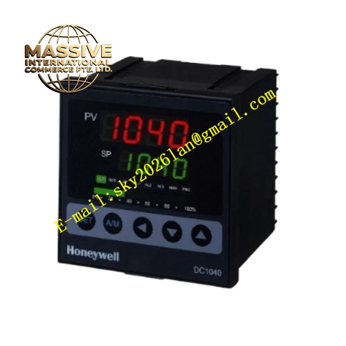
Description
Honeywell DC1040CR-301-000-E
Technical Specifications
- Input types: J, K, T thermocouples, Pt100 RTD
- Output types: SPDT relay 2 A / 250 V AC, plus 4–20 mA analog modulating output
- Supply voltage: 100–240 V AC universal
- Display: Dual 4-digit LCD
- Control modes: On/off, PID auto-tune
- Accuracy: ±0.3% full scale
- Cutout size: 48 x 48 mm panel mount
Functional Features Dual output configuration: relay for on/off alarm or stage control, analog output for proportional modulation. PID auto-tune calculates optimal parameters for modulating control loops. Universal configurable sensor input. Two independent alarm thresholds. Front keypad lock prevents unauthorized setpoint changes. Configurable output mapping, assigns process value range to 4–20 mA output.
Application Scenarios Proportional electric heating valve control Variable speed heater power regulation Process temperature loops requiring continuous modulation Upgrade replacement for relay-output controllers that cause temperature oscillation
Performance Parameters
- Analog output accuracy: ±0.5% full scale
- Output load impedance: ≤600 Ω for 4–20 mA loop
- Control accuracy: ±0.3 °C for PID operation
- Sampling cycle: 0.5 seconds
- Operating temperature: 0 °C to +55 °C
Material Composition Flame retardant ABS front bezel Aluminum mounting chassis SSR drive output circuit Glass LCD window Stainless mounting clips Screw terminal block
Structural Features Square 48 x 48 mm panel mount form. Front LCD and pushbutton keypad. Rear terminals grouped by supply, sensor, relay output and analog output. Same cutout dimensions as standard DC1040, for direct panel replacement.
Working Principle The controller reads temperature sensor input via the ADC, comparing process value to setpoint. PID calculation outputs a 4–20 mA signal proportional to required control effort, sent to the external proportional valve or heater power controller. The relay output triggers as an alarm or secondary heat stage. Auto-tuning mode observes process response to determine optimal PID parameters for the modulating loop.
Installation Requirements Mount into the 48 x 48 mm panel cutout. Wire analog output using shielded cable, single-point shield grounding. Configure sensor type, output mode and setpoint range in the menu. Verify analog output scales 4 mA at 0% control, 20 mA at 100% control.
Usage Notes Analog output loop load must not exceed 600 Ω, higher impedance causes signal dropout. Shielded cable for analog output prevents EMI-induced signal noise. Do not switch high-current loads directly on the analog output terminals. Periodically re-run auto-tune after process load changes to maintain control accuracy.







