



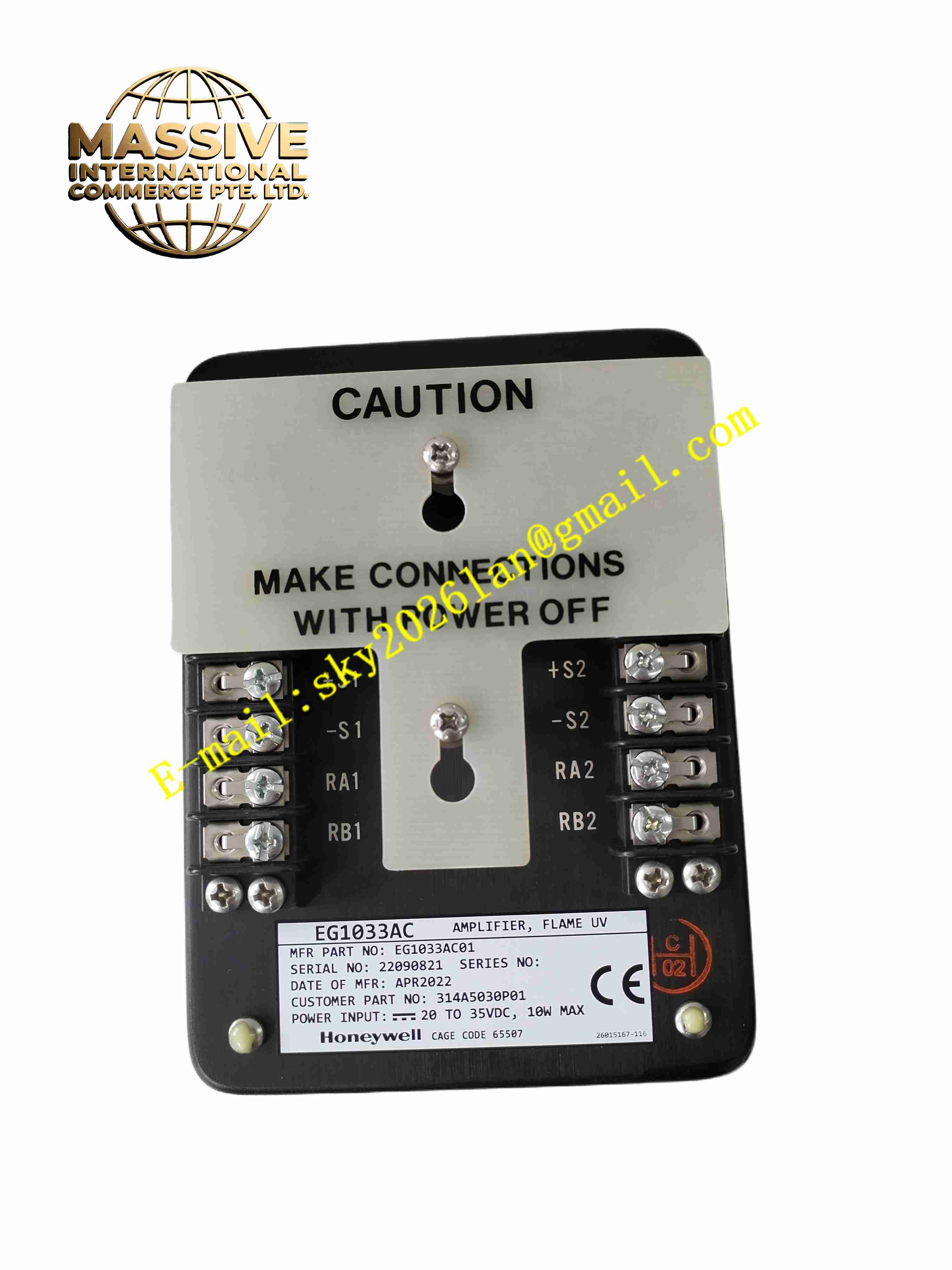
Description
Honeywell EG1033AC01
Technical Specifications
- Product Type: Flame signal amplifier module
- Power Supply: 120 VAC or 230 VAC
- Sensor Input: UV flame detector signal input
- Response Time: Fast flame loss detection within milliseconds
- Output Type: Relay contact flame status output
- Protection Rating: IP20
- Operating Temperature: -20 °C to +60 °C
- Mounting: DIN rail mounting
- Certification: FM, CE, IEC 61508 SIL capable
Functional Features
- High gain amplification of weak UV flame detector signals.
- Fast flame loss detection to trigger burner safety shutdown upon flame failure.
- Built-in self-check circuit to verify amplifier and sensor health.
- Adjustable signal sensitivity to match different burner flame characteristics.
- Relay contact output transfers flame present or flame fault status to BMS controller.
- LED indicator shows flame signal strength and module fault state.
- Rejects false signal caused by hot refractory or background radiation.
- Noise filtering reduces interference from industrial lighting and electrical equipment.
- Compact DIN rail design for installation inside burner control cabinet.
- Flame signal strength analog output for continuous monitoring.
Application Scenarios
- Boiler burner management systems
- Furnace and heater flame safety monitoring
- Refinery process burner flame detection
- Gas turbine auxiliary burner monitoring
- Industrial kiln combustion safety interlock
Material Composition
- Housing: Flame-retardant plastic enclosure
- Main PCB: FR4 printed circuit board with conformal coating
- Signal amplifier: High precision operational amplifier circuit
- Relay: Sealed safety relay for flame status output
- Terminal block: Copper alloy screw terminals
- LED indicators: Visual flame and fault status LEDs
Structural Characteristics
- Standard DIN rail vertical modular housing.
- Front panel fitted with LED indicators for flame signal and fault.
- Upper terminals for AC power supply and flame sensor input wiring.
- Lower terminals for flame status relay output wiring.
- Internal circuit isolates high voltage power section and low level sensor signal circuit.
- Rear DIN rail locking buckle for cabinet installation.
Working Principle UV flame detector captures ultraviolet radiation emitted by flame and generates weak electrical signal. The EG1033AC01 amplifies this low-level signal and filters noise. The internal comparator evaluates signal amplitude against preset threshold. When flame signal exceeds threshold, the module activates flame-present relay output. If flame signal drops below threshold for preset time, the module de-energizes relay to send flame failure trip signal to burner safety controller. Built-in self-test circuit checks amplifier circuit integrity continuously.
Installation Requirements
- Install on DIN rail inside burner control cabinet.
- Use shielded twisted pair cable for flame detector sensor wiring.
- Keep sensor cable routed away from high-current ignition cables.
- Apply correct AC supply voltage matching module rating.
- Adjust flame sensitivity during burner commissioning.
- Perform flame simulation test to verify flame failure trip function.
- Complete cabinet protective earth connection.
Usage Notes
- Do not run flame sensor cable alongside high voltage ignition wiring.
- Keep cabinet free of dust and oil contamination.
- Perform periodic flame test and self-test as part of BMS safety procedure.
- Replace UV detector tube when signal strength drops significantly.
- Do not modify internal amplifier circuit.
- Disconnect power supply before removing module.
- Verify relay contact integrity during routine maintenance.







