



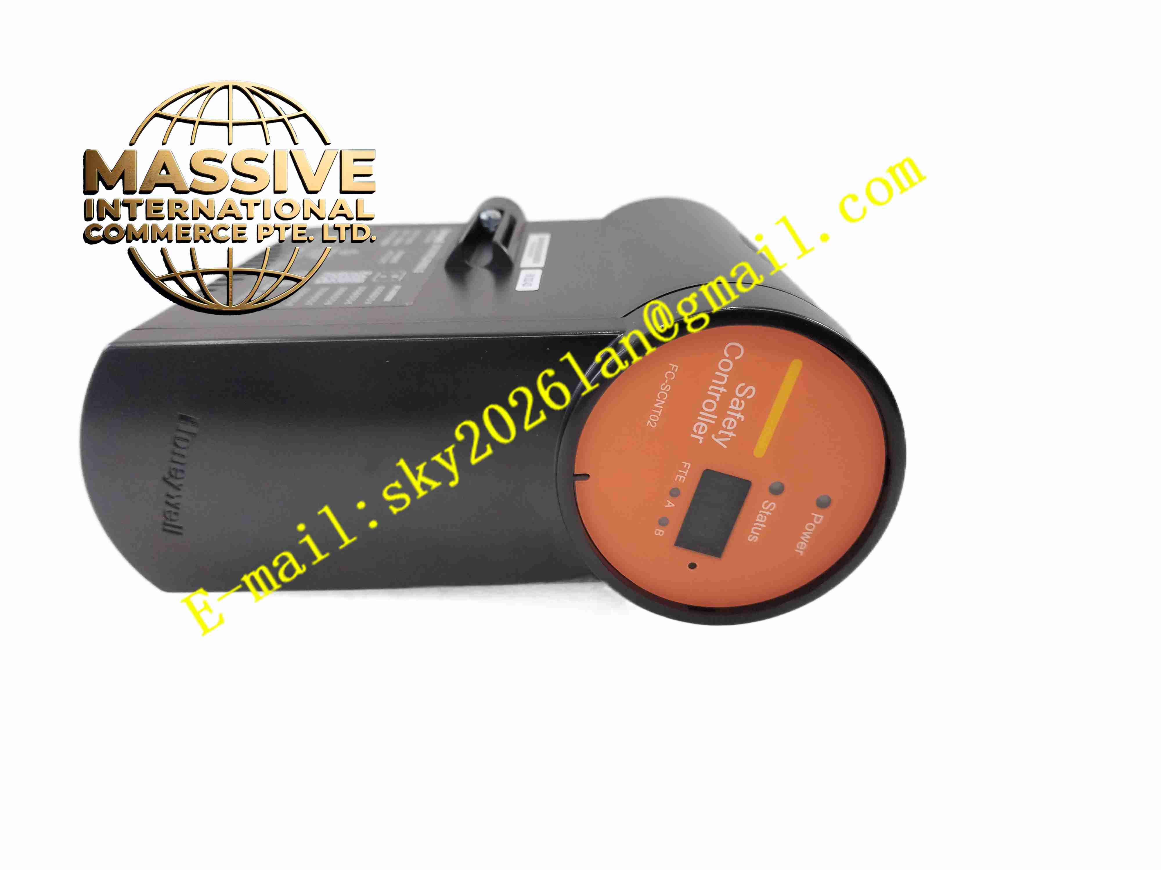
Description
Honeywell FC-SCNT01
Technical Specifications
- Product Type: Safety pulse counter module
- Input Channels: Multi-channel pulse input
- Max Counting Frequency: Up to 150kHz
- Signal Type: 24VDC pulse, incremental encoder A/B phase signal
- Safety Certification: IEC 61508 SIL2 / SIL3 applicable
- Bus Interface: Safety Manager rack backplane bus
- Diagnostic Functions: Input signal fault, power monitoring, internal self-test
- Protection Rating: IP20
- Operating Temperature: -10 °C to +60 °C
- Mounting Method: Rack slot mounting
- Cooling Method: Passive convection cooling
Functional Features
- High speed pulse counting and incremental encoder direction discrimination.
- Supports quadrature encoder ×1, ×2, ×4 counting modes for position and speed measurement.
- Dual redundant counting circuit cross verifies pulse data to meet safety integrity requirement.
- Continuous hardware self-test runs during power-up and normal operation.
- LED indicators display module power, running status and input channel fault.
- Overvoltage and overcurrent protection for pulse input terminals.
- Captures high resolution timestamp for pulse events for sequence of event recording.
- Supports preset counting threshold for safety trip trigger.
- Fault information uploads to safety controller for alarm and event logging.
- FC-SCNT02 serves as compatible replacement spare part for FC-SCNT01.
Application Scenarios
- Turbine and compressor overspeed safety protection system pulse measurement
- Pipeline flow meter cumulative volume safety monitoring
- Conveyor machine speed safety interlock in chemical plant
- Rotating machinery shaft speed safety detection
- Skid mounted equipment position and motion safety monitoring
Material Composition
- Housing: Flame-retardant polycarbonate plastic casing
- Main PCB: FR4 high reliability printed circuit board with conformal coating
- Processing components: Safety certified counter logic chips
- Isolation components: Optocoupler isolation chips
- Backplane connector: Gold-plated copper edge pins
- Terminal interface: Copper alloy contact terminals for pulse signal wiring
Structural Characteristics
- Standard single slot vertical rack module structure for Safety Manager rack.
- Front panel equipped with LED indicators for module and channel working state.
- Rear gold-plated edge connector inserts into rack safety backplane bus.
- Internal dual counting circuits run independently and cross-compare calculation results.
- Internal isolation barrier separates field pulse circuit and safety logic circuit.
- Compact layout reduces electromagnetic interference from pulse signals.
Working Principle Pulse signals from encoders or flow transmitters enter input channels and pass through galvanic isolation circuit. Dual independent counter circuits sample pulse edges synchronously and calculate pulse frequency, rotation speed and accumulated count value. The two sets of measurement results are cross-compared. If result mismatch occurs, the module triggers fault alarm and sends fault message to safety CPU. Valid counting data is transmitted to safety controller for safety logic judgment.
Installation Requirements
- Install FC-SCNT01 module into designated slot of Safety Manager rack.
- Use shielded twisted pair cable for encoder and pulse sensor wiring.
- Separate pulse signal cable from servo and high power motor cables.
- Complete protective earth connection for rack and cabinet.
- Configure counting mode, frequency filter and preset threshold in Safety Builder software.
- Perform pulse signal simulation test after wiring completion.
- Verify backplane connector contact integrity before power on.
Usage Notes
- Do not hot plug module when rack main power remains active.
- Do not connect pulse signal source with voltage beyond rated specification.
- Keep cabinet dry and free of oil mist and conductive dust.
- Check pulse cable shielding and grounding periodically under vibration environment.
- Execute periodic SIL proof test for counting channels.
- Use anti-static protection during spare module handling.
- Replace module immediately when permanent hardware fault appears.







