



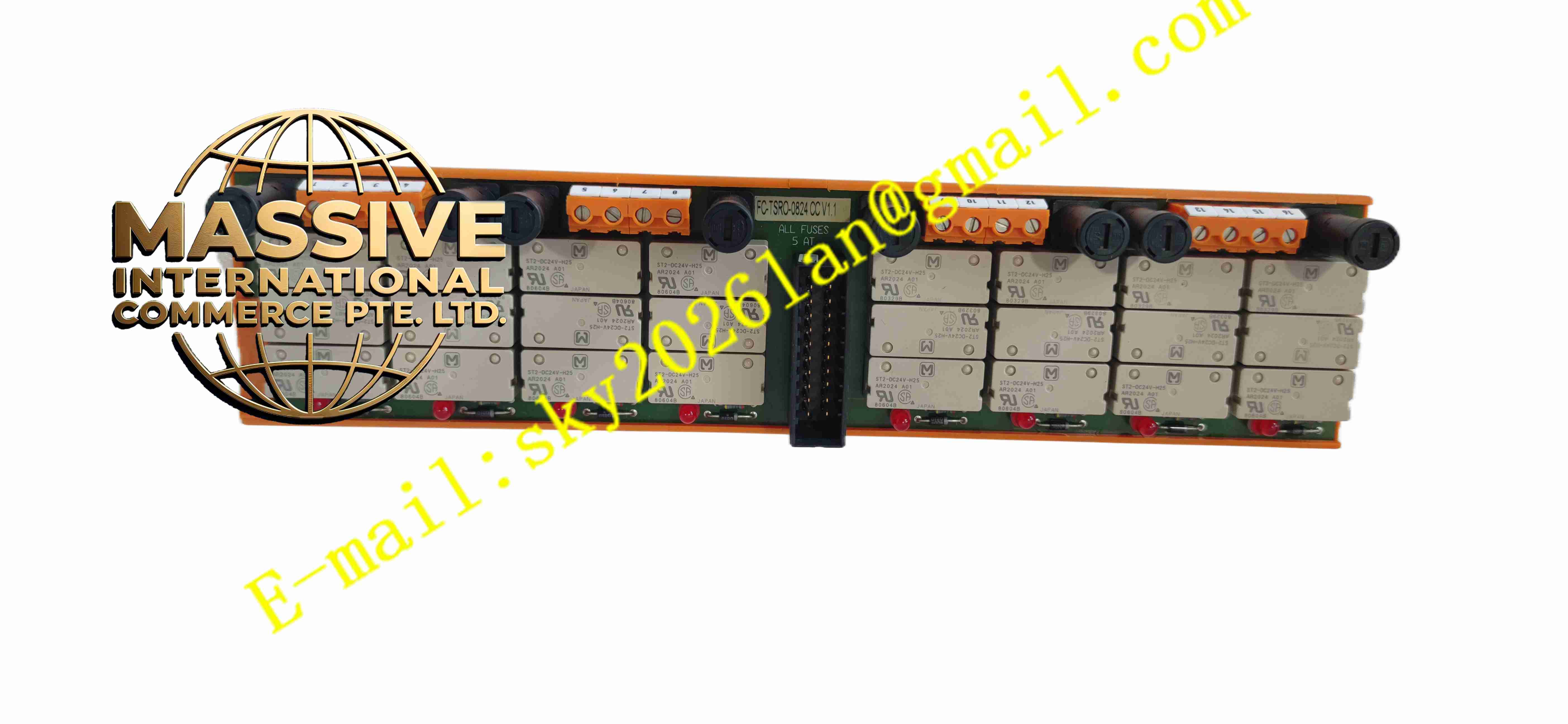
Description
Honeywell FC-TSRO-0824
Technical Specifications
- Product Type: Safety relay output termination assembly
- Channel Count: 8 relay output channels
- Contact Type: Dry contact relay output
- Contact Rating: Rated for industrial safety load switching
- Built-in Components: Safety relays, per-channel fuses, surge suppression devices
- Cable Interface: SIC ribbon cable connector to safety output module
- Terminal Type: Screw terminal block
- Protection Rating: IP20
- Operating Temperature: -10 °C to +60 °C
- Mounting Method: DIN rail mounting
Functional Features
- 8-channel safety relay dry contact output for high power field safety load control.
- Galvanic isolation between low voltage safety control circuit and field high voltage circuit.
- Per-channel fuse protection limits fault current on field load side.
- Built-in surge suppression absorbs inductive load back EMF during contact switching.
- SIC ribbon cable interface connects assembly to Safety Manager safety output module.
- Front panel LED indicators display relay power and contact state.
- Screw terminal block provides reliable wiring connection for field high voltage loads.
- Continuous relay contact state feedback returns to safety output module for diagnosis.
- Compact DIN rail mounting structure saves cabinet installation space.
- Relay contacts switch to safe state automatically upon loss of control power.
Application Scenarios
- Petrochemical plant ESD high power safety circuit relay control
- Fire and gas system high voltage alarm equipment relay drive
- Power plant boiler burner management safety circuit isolation relay
- Offshore platform safety instrumented system high power load interlock
- Chemical plant safety skid high voltage equipment safety trip relay control
Material Composition
- Housing: Flame-retardant polycarbonate plastic casing
- Terminal block: Tin-plated copper alloy screw terminals
- PCB: FR4 high reliability printed circuit board
- Switching components: SIL rated safety electromagnetic relays
- Protection components: Channel fuses and surge suppression diodes
- Cable connector: Gold-plated copper contact pins for SIC ribbon cable
- Mounting bracket: Steel DIN rail clip
Structural Characteristics
- Compact horizontal DIN rail mounting structure.
- Front screw terminals for field high voltage load wiring.
- Rear SIC ribbon cable connector links to rack safety output module.
- Each channel has independent safety relay, fuse and surge suppression circuit.
- Internal isolation barrier separates low voltage safety control circuit and high voltage field circuit.
- Front panel LED indicators show relay energized and contact status.
Working Principle Low voltage safety control signal from safety output module transmits through SIC ribbon cable to FC-TSRO-0824. The control signal energizes or de-energizes safety relay coil. Relay dry contact closes or opens to switch field high voltage load circuit. Contact feedback signal returns to safety output module for contact state diagnosis. When coil power is lost, relay contacts switch to predefined safe state. Fuse and surge suppression components protect circuit from overcurrent and electrical transient.
Installation Requirements
- Mount FC-TSRO-0824 assembly on standard 35mm DIN rail inside control cabinet.
- Separate high voltage field load wiring from low voltage safety control wiring.
- Tighten terminal screws to specified torque value.
- Connect SIC ribbon cable to corresponding safety output module correctly.
- Complete protective earth connection for assembly housing.
- Verify load current stays within relay contact rated range.
- Perform relay switching test and contact feedback test after wiring completion.
Usage Notes
- Cut off both field high voltage load power and control power before maintenance.
- Replace fuses with same rated specification only.
- Do not exceed relay contact voltage and current rating.
- Keep cabinet dry and free of conductive dust and corrosive gas.
- Check relay contact condition periodically during routine maintenance.
- Disconnect SIC ribbon cable before insulation resistance test.
- Replace assembly immediately when relay contact burnout or permanent circuit fault occurs.







