



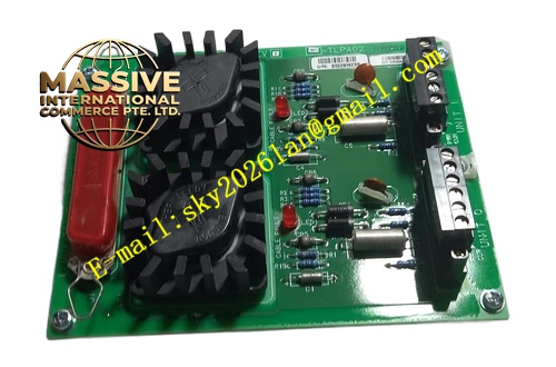
Description
Honeywell MC-TLPA02
Technical Specifications
- Input power: Dual 120 VAC main supply and 24 VDC backup supply inputs
- Output branches: 8 independently protected output circuits, supplying LCN communication boards, fans, indicator lights and local panels
- Per-branch rated current: 5 A
- Protection element: Slow-blow glass tube fuse, independent protection per branch
- Power conversion efficiency: ≥92%
- Operating temperature: 0 °C to +60 °C
- Relative humidity: 5% to 95% non-condensing
- Mounting: Screw-fixed in the lower cabinet power compartment
Functional Features Dual-power automatic switchover, backup 24 VDC supply activates immediately when main 120 VAC supply fails. Independent fuse per branch, single-branch short circuit does not disrupt power to remaining circuits. On-board LED per branch indicates output power status, simplifies branch-level fault troubleshooting. On-board EMI filter circuit suppresses high-frequency noise on power lines, preventing interference to sensitive communication boards. Dedicated grounding bus bar collects all on-board circuit grounds for single-point connection to cabinet protective ground. Silk-screen labeling clearly marks input and output definitions, reduces field wiring error rate.
Application Scenarios Power distribution for TPS system LCN cabinets Spare part replacement for burnt power boards and no-output branch faults in legacy TPS cabinets Power loop remediation for communication board resets caused by power interference New TPS cabinet power compartment assembly Power reliability upgrade for unmanned remote station LCN systems
Performance Parameters
- Power switchover time: ≤2 ms, no perceptible disturbance to connected loads
- Output voltage drop: ≤0.3 V at full load
- Fuse blow response: ≤10 ms
- Insulation resistance: ≥1000 MΩ
- Surge tolerance: ±6 kV contact electrostatic discharge
Material Composition FR4 flame retardant PCB substrate Tin-plated copper high-current traces Slow-blow glass tube fuse array Common-mode EMI filter inductor Green status indicator LEDs Tin-plated copper screw terminals Powder-coated cold rolled steel mounting bracket
Structural Features Long rectangular PCB form factor, dimensions matched to the TPS lower cabinet power compartment. Front face arranges input/output screw terminals and fuse holders. Corresponding status LED positioned next to each output branch. Mounting holes on board edge lock to cabinet uprights. Physical partition between high-voltage 120 VAC area and low-voltage 24 V area.
Working Principle Cabinet incoming 120 VAC power connects to the adapter board, passes through EMI filter and inrush current limiting circuit, then distributes to 4 output branches powering connected loads. 24 VDC backup supply connects to the switchover circuit; when 120 VAC main supply fails, the diode switchover circuit automatically connects backup supply to the power bus, maintaining continuous load operation. Each output loop is series-connected with a fuse; branch load short circuit blows the fuse, cutting power to the affected branch to protect boards and cabling. Status LEDs parallel across each output illuminate to indicate live output.
Installation Requirements Complete all wiring operations only after de-energizing the cabinet. Strictly follow silk-screen markings for 120 VAC input and 24 VDC backup supply connection, never reverse phase sequence. Connect grounding terminal reliably to cabinet protective ground, ground resistance ≤0.1 Ω. Use cable gauge matched to 5 A branch rating, terminate connections securely. Check LED status per branch after power-up, confirm all branches output normally.
Usage Notes When replacing fuses, use only matched slow-blow components; standard fast-blow fuses blow incorrectly during startup inrush. Insulate 120 VAC high-voltage wiring areas to avoid accidental electric shock. When a branch overheats repeatedly, disconnect the load, locate the short circuit before restoring power. Never short-circuit on-board fuses, this removes overcurrent protection and creates wiring fire risk.







